Contents tagged with tit_hajózástörténeti_modellező_és_hagyományőrző_egyesület

  • Fourth funnel of OLYMPIC-class liners

    Tags: titanic, balogh, tit, tit_hajózástörténeti_modellező_és_hagyományőrző_egyesület, tit_hmhe, hajózástörténeti_tagozat, Ocean_liners, Encyclopedia_of_ocean_liners

    With regard to ocean liners built with many funnels, it is widely believed that in older times many funnels were needed only because the poor efficiency of early boilers required this. However, there are many examples of large numbers of funnels being used even after they were no longer absolutely necessary due to the development of boilers. In the present study, we recall these examples.

    Introduction:

    The silhouette of the ships has been defined for centuries by a plethora of high masts and sails, making it recognizable from afar. As steam propulsion gained more and more ground in ocean-going shipping, the masts and sails disappeared and were gradually replaced by ships that were emitting dense smoke and soot, or just friendly white steam. Finally the thin and tall, or even thick and squat funnels, which lined up on upper deck of the huge passenger liners, had became characteristic hallmarks, just on the same way as the most striking element of the human face is the nose.

    A total of only 14 four-funnelled ocean liners have been built in the history of shipping, although the GREAT EASTERN is sometimes listed here, but it was originally a five-stacker and was only converted to a four-funnelled in cable-laying period of it's service time. However, each of them did not really need four funnels, including the White Star Line's famous OLYMPIC-class trio (OLYMPIC, TITANIC, GIGANTIC - later BRITANNIC II).

    001_29.jpg

    Fig. 1.: That 14 four-funnel ocean liners which served in shipping companies of different nations through the maritime history. (created by Dr. Tamás Balogh).


    001_3_1.jpg

    Fig. 2. and 3.: First four-funnelled ships were warships: the H.M.S. TERRIBLE (1845-1879) the largest steam-powered wooden paddle wheel frigate built for the Royal Navy, and the U.S.S. WAMPANOAG (1864-1885), a screw frigatedesigned to be the fastest in the world, were intended for use in hit-and-run operations against British ports and commerce in the event of war (this type of warships widely known as cruisers later). The WAMPANOAG was a speed-recorder of the age with it's18 knots. (Source: to the TERRIBLE here, to the WAMPANOAG here and here.)


    001_4_1.jpg

    Fig. 4., 5., 6., 7., 8. and 9.: First four-funnelled civilian ships were was the iron paddle-steamers of the ULSTER-class which performed at a speed of 14 knots - ULSTER (1860-1897), MUNSTER (1860-1896), LEINSTER (1860-1896), CONNAUGHT (1860-1897) - built by the Laird's ship builders of Birkenhead for the City of Dublin Steam Pocket Co., and the BEN-MY-CHREE (1875-1906) built by Barrow Shipbuilding Co. for Isle of Man Steam Packet Company.


    001_5_1.jpg

    Fig. 10., 11. and 12.: Plan and builder's model of the very first four-funnelled ocean liner from 1890. A German engineer employed by Fairfield Shipbuildingand Engineering Company, in Govan, Scotland, Robert Zimmermann, made for GUION LINE a new design for their new record breaker. Stephen Barker Guion (1820–1885) has died, and the then financial instable line, transformed into an incorporation, tried to get a new record vessel after OREGON went back to the builder, who sold it to CUNARD. The newbuild contract never materialized. Zimmermann went back to Germany and seven years later the first four-funnelled ocean liner came into service under German flag.


    In the present study, we are looking for an answer to what has led designers to use such components, which are indifferent to the ship's operability, and that ships with dummy funnels, especially those in the OLYMPIC-class, were really only self-serving results of designer's or customer's arbitrary, without any rationate and practical function?

    001_28.jpg

    Fig. 13.: Boiler room and fuunnel-arrangement of the famous GREAT EASTERN 1858-1890 (Source: Library of Congress).


    I.) On the practical and aesthetic significance of funnels:

    The primary purpose of funnel(s) on steamships is to remove smoke (and smoke gases), heat and excess steam from the boiler(s) located down, in the boiler room(s). As the size of ocean liners increased, more and more boilers were used.

    The boilers were connected directly to the funnels in the middle of the 19th century. It was the so-called simple smoke-exhausting system. However, as the number of boilers increased, smoke-gas exhausting required more and more differentiated technical solutions, since it was also necessary to find a way to connect the flue pipes of those boilers which were located further from the funnel uptakes (had to abandon those previous solution, according to which 1-2, or maximum 4 boilers standing under a certain funnel are connected into the same funnel uptake, since an unlimited number of funnels could not be placed on the upper deck, if passengers should have accommodated too).

    The problem is well illustrated by the fact that the GREAT EASTERN (which was the largest ship in the world for 40 years, and had fundamentally influenced the mindset of designers for decades), had only 10 boilers initially with 5, then (after reducing the number of boilers) with 4 functioning funnels, but the ships of the OLYMPIC-class had 29 boilers per ship with 3 funnels! The technical task to be solved was therefore to divert the combustion products of the boilers located further away from the funnel-uptakes to the funnels as well. In doing so, the horizontal sections had to be avoided, which would have led to a stagnation of the flow of flue gases, a cessation of ventilation, and possibly a return to the combustion chamber (thus reducing the efficiency of the combustion).

    The solution was the development of a complex boiler exhaust assembly system for boilers in the last decade of the 19th and the first of the 20th century. This is consisted of two basic structural elements, between the boilers in the bottom of the vessel and the funnels on the upper deck: (1) special-shaped ventillation shafts (or boiler uptakes) which connect gas exit flanges on the upper part of boilers with the lower part of the funnel uptakes, and (2) the actual vertical funnel -or smoke shafts (i.e. funnel uptakes).

    002_25.jpg

    Figs. 14. and 15.: GREAT EASTERN’s simple and OLYMPI’s complex boiler exhaust assembly system (blue: boiler, green: boiler uptakes, red: funnel uptakes). (Source: Science Museum and Bruce Beveridge)


    By the end of the 19th century, the long rectangular, box-shaped (so-called locomotive) boilers used in steam locomotives had been replaced by cylindrical boilers for ships. According to the widespread practice, a maximum of two rows of single- or double-ended boilers (which had fireplaces at both ends, ie heated from both sides) were connected to one funnel with 3-5 boilers per row. Depending on the number of boilers and the size of the ships, this solution was first used by the Germans to build a four-funnelled ocean liner, which was named KAISER WILHELM der GROSSE (1897-1914). In Germany, it became model of an ocean liner-series (owned by Norddeutscher Lloyd, which built 3 or more ships based on it's plans, but even the great rival HAPAG - Hamburg-Amerikanische Paketafahrt Aktiengesellschaft - used the plans of this ship to build a fast steamer called DEUTSCHLAND).

    00456.jpg

    Figs. 16., 17. and 18.: Boiler- and funnel-arrrangement of KAISER WILHELM der GROSSE, its sister ship, KRONPRINZ WILHELM (above) and DEUTSCHLAND (middle) and KAISER WILHELM II and its sister ship, KRONZPRINZESSIN CECILIE (below). (Source: Collection of Dr. Tamás Balogh.)


    In the case of German ships, however, the number of funnels has clearly been adapted to aspects other than technical necessity. In their case, unlike the practice of the time, there were not 2-2 rows of single- or double-ended boilers connected to the funnels, but fewer!

    1) In the case of KAISER WILHELM der GROSSE (and its sister ship), only 1-1 rows of double-ended boilers were connected to 3 of the 4 funnels (2 rows of boilers were connected only to the last last funnel, but into one of these rows only single-ended boilers installed).

    2) In the case of DEUSCHLAND, although 2-2 rows of boilers were already connected to all 4 funnels, there was always only single-ended boilers in one row.

    3) Finally, in the case of KAISER WILHELM II (and its sister ship), there was again only one row of double-ended boilers under 1 of the 4 funnels, while in one of each rows of boilers under the other funnels contained only single-ended boilers.

    In other words, while it was already possible at that time to connect 2 rows of double-ended boilers to 1 funnel (with 3-5 boilers per row), only half of this amount (up to one and a half times) was connected to 1-1 funnels on German ships. That is, the flue gas extraction of the boilers - if all the possibilities provided by the technical standards of the age were used to the maximum - could have been solved with fewer funnels! In light of this, the question may arise: what justified this type of funnel-arrangement? The answer is simple: advertising!

    By the first years of the 20th century, the market for transoceanic passenger taffic had changed significantly. The transport of masses of emigrants from Europe to America from the second half of the 19th century onwards, more and more small and medium-sized European shipping companies were set up. Their presence was a challenge for the large national shipping companies, regarding they ordered far more ships than ever before, while - in the supply market - ticket prices were falling consequently. In order to stay afloat, companies have been lowering their prices and relentlessly cutting tariffs to secure a place in the competition. Thus, in many cases, they did not even generate enough revenue for the maintainance costs of their ships, let alone pay dividends to their shareholders.

    A typical case of absorption was recognized by a U.S. financier, John Pierpoint Morgan, who – with the transformation of the International Navigation Co., established in 1871 to merge U.S. transatlantic shipping companies with strong financial support from the Pennsylvania Railroad Company and various banks – acquired shares in the largest European shipping companies (including the English White Star Line) by 1902, and has entered into a co-operation agreement (we would now say a market-sharing agreement) with the German HAPAG and Norddeutscher Lloyd. The International Mercantile Marine Co., which was formed at this time, has since then rationalized the shipbuilding programs of its member companies, but until that the competition was almost unrestricted and ruthless.

    In this situation, all that mattered was for the companies to catch passengers and persuade them to choose their ships for the transatlantic crossing rather than ships of the rival companies. As the 5-7 day voyage was still one of the most dangerous modes of travel at the time (the entry "disappeared at sea" was in too many registers), safety, speed and strength were those primary considerations for the passengers for their decisions. So the German designers set out to design ships that, with their appearance, suggest safety, speed and strength. When German ships actually won one by one the award for fastest Atlantic crossing - the famous Blue Ribbon - four funnel, which originally was just a marketing trick, became a brand and a symbol of speed and safety. Therefore, shipping companies have made every effort in order to be able to put four-funelled ocean-liners into service…

    All right, but exactly what?

    1) For example, they designed – or redesigned – their ships (which were still in the design phase) on that way, so that their boiler-arrangement will be as such that 4 funnels must be built in all conditions (the LUSITANIA and MAURETANIA, which originally designed as three-stacker, thus became four).

    2) Or they built dummy funnels on their ships (as in the case of the OLYMPIC-class) simply just to have four funnels, in order to gave the impression of strength with them, by making their ship’ appearance more impressive.

    Nevertheless the construction of the four-funnelled oceanliners used by competing shipping companies covered a very short period of time, only 25 years from the construction of the KAISER WILHELM der GROSSE in 1897 to the construction of the SS WINDSOR CATLE in 1922. In this quarter of a century, the reason for the use of a larger number of funnels, although in some cases undoubtedly necessary, remained largely symbolic.

    007_9.jpg

    Fig. 19.: The LUSITANIA (and its sister ship, the MAURETANIA) would have been built with three funnels according to the first plans in 1903. (Source: wikihmong.com)


    However, the power and the prestige of the four funnels (which almost created style and fashion at the beginning of the 20th century) began to decline shortly after the First World War and then quickly disappeared. The flagships of the fleets of the large shipping companies, including the IMPERATOR, NORMANDIE and QUEEN MARY, had only three funnels (and often almost even that was unnecessary, since the size and performance of the boilers increased, so the same performance could be achieved with fewer boilers and funnels). The increase in the efficiency of shipbuilding, and the need to preserve (and possibly increase) the space available to passengers, has eventually led to the fact that oceanliners built in the years before the Second World War were only built with a maximum of two funnels, like in case of the BREMEN and EUROPA, the REX and CONTE di SAVOIA, and the MAURETANIA (II.) and QUEEN ELISABETH. And today's modern passenger ships carry only a single stack uniformly…

    008_10.jpg
    Fig. 20.: Final boiler- and funnel-arrangement of the LUSITANIA (and its sister ship, the MAURETANIA) from 1907. (Source: Illustrated London News, Courtesy of Péter Könczöl.)


    II.) OLYMPIC-class dummy funnels - is a "dummy" funnel really disfunctional?

    Units of the OLYMPIC class originally evoking the outline of the latest ocean liners built before them for the White Star Line (i.e. the "Big Four" - ADRIATIC, BALTIC, CEDRIC and CELTIC), as they would have been four- or three-masted ocean liners, with a superstructure split into several parts and only three (!) funnels. However, according to the first preliminary design which made after the construction of LUSITANIA and MAURETANIA in the summer of 1907, were soon replaced by the designs of a much larger and more elegant four-funnelled ship, he led the combustion products of the boilers to the open air. The R.M.S. OLYMPIC and its two sisterships thus eventually had four recognizable, elegant funnels, the first three of which led the combustion flue of the boilers to the open air.

    0091011.jpg

    Figs. 21., 22. and 23.: Plans of the R.M.S. BALTIC (above), first sketches of the OLYPMIC from 1907 (middle) and view of the ship (below). (Source: Wikimedia, The New York Times, March, 15.1908, Pinterest).


    012013.jpg


    014_015.jpg

    Figs. 24., 25., 26. and 27.: Boiler and funnel arrangement of the OLYMPIC on the final plans of the ship. (Source: Dr. Tamás Balogh.)


    016_017_018a.jpg

    Figs. 28., 29. and 30.: Spider-like boiler uptakes for the OLYMPIC-class that conveyed flue gases and soot to the funnel uptakes. The size of these structures that are about to be completed is a good indication of how much space they needed over the boilers (Source: Samuel HalpernParks Stephenson). 


    A boiler uptakes of 29 shafts, reminiscent of a giant spider, connected to the first three funnels was available for smoke extraction. In contrast, the fourth funnel in the OLYMPIC class (often referred to briefly as a “dummy” funnel) was used for ventilation, ie the fourth funnel was part of the ventilation system, namely it had to be used for the ventilation for the engine room and had to drain the combustion products from the fireplace of the first class smoking room. 

    When OLYPMIC's boilers were converted to burn oil instead of coal in the 1920s, a fan was built into the fourth funnel to extract the flammable gases formed in the oil tanks. The fittings and equipment in the funnel were accessible and maintained by means of ladders built inside the funnel, which help for mechanics in cleaning or even in maintainance.

    The elliptical cross-section funnels were 24 feet, 6 inches, and 19 feet in diameter, height were 70 feet from the boat deck, 150 feet from the waterline, and had an angle of 11 degrees. Each funnel was held by six-six steel wire (wrapped with rope) from each side, which were attached to rims placed on the reinforced lower part of the black-painted funnel collars. The funnel itself was painted buff, the usual White Star Line livery, except for the top quarter, which was painted black to mask the discoloration caused by soot on the funnel collar.

    018019020.jpgFigs. 31., 32. and 33.: TITANIC funnel-arrangement and fourth funnel on the ship's plans (Source: Daily Mail, The Hitory Blog).


    021_1.jpg

    Fig. 34.: The dummy funnel of the OLYMPIC-class did not determined by aesthetics only. The rear funnel served the following functions: 1) ventilated air to/from the ship’s medical compartment, 2) ventilated air to/from the ship’s engine room, 3) ventilated air to/from the 1st and 2nd Class kitchens, 4) and was a chimney for the 1st Class smoking room fireplace. (Source Illustrated London News)

    022_028.jpg

    Figs. 35., 36., 37., 38., 39., 40., and 41.: Above the first three funnels of the OLYMPIC-class liners and the fourth funnel in the middle. The bottom three images were taken from the top of the fourth funnel of the OLYMPIC in the 1920s.


    III.) Were other ships built with dummy funnels?

    That's right! Even not one! As mentioned in the introduction to the study, not all of the 14 four-funnelled liners would have needed four funnels! In fact of the 14 ships, only 11 actually needed four funnels to discharge the combustion products from their boilers.

    At the same time, dummy funnels for the White Star Line’s three OLYMPIC-class ships has long been the subject of debate. The German website on the work of the German Shipbuilding Technical Society (Schiffsbautechnische Gesellschaft) from 1901 to 1930, for example, traces the aesthetic debate of the fourth dummy funnel of the OLYMPIC class in 1917 (!).

    Why this renowned society of German civil and naval shipbuilding engineers considered this topic important in the third year of the war, and why the abandonment of the fourth funnel still met with fierce resistance after the construction of the first two ships of the three-funnelled IMPERATOR-class, is a mystery.

    The translation of the description commemorating the 1917 debate is as follows:

    "Prof. Lienau [professor at the Royal Prussian Technical College in Danzig, today Gdansk, Poland], gave a lecture on the fourth funnel of the Olympic / Titanic, which was only a dummy funnel, and then discussed his proposal for another three-funnelled fast steamer, which others strongly opposed it."


    029a.jpg

    Fig. 42.: Otto Lienau's demonstration (Source: Otto Lienau: Schiffbau als Kunst, in.: Jahrbuch der Schiffbautechnischen Gesellschaft, 1918. 328. o., collection of Dr. Tamás Balogh).


    However, out of the 11 real four-funnelled ocean-going steamers mentioned, 7 (the 4 KAISER-class ships of the German Norddeutscher Lloyd, the DEUTCHLAND of the German HAPAG Line, the ARUNDEL CASTLE and WINDSOR CASTLE of the british Union-Castle Line) only had four funnels just because their plans had been modified such a way, although two funnels would have been enough for them. Funnels that originally served for boilers that actually operate in two boiler rooms were separated per boilers, so instead of one funnel per boiler room they received two funnels (one per boiler), that is, in their case, artificially (not because of technical necessity) four funnels were created.

    03031.jpg

    Figs. 43. and 44.: WINDSOR CASTLE ocean liner in its original condition and after reconstruction. There was no need for four funnels! (Source: Wikipedia)


    2 ships out of 11 (the LUSITANIA and MAURETANIA of the British Cunard Line), only three funnels were originally designed in the same way as the first plans of the OLYMPIC-class, and only due to the success of the German four-stackers - so only for advertising reasons - they decided to change the plans and order four-funnelled ocean liners. All in all, therefore, only 2 of the 14 vessels actually and indisputably had four funnels from the very first stage of design: in case of AQUITANIA of the Cunard Line and FRANCE (II) of the Compaigne Générale Transatlantique ('Transat'), although the real four-funnelled nature of the latter is debatable given the boiler arrangement.

    032033.jpg

    Figs. 45. and 46.: Longitudinal section of the only real four-stackers, the AQUITANIA (above) and the FRANCE (II.). (Source: Dr. Tamás Balogh)


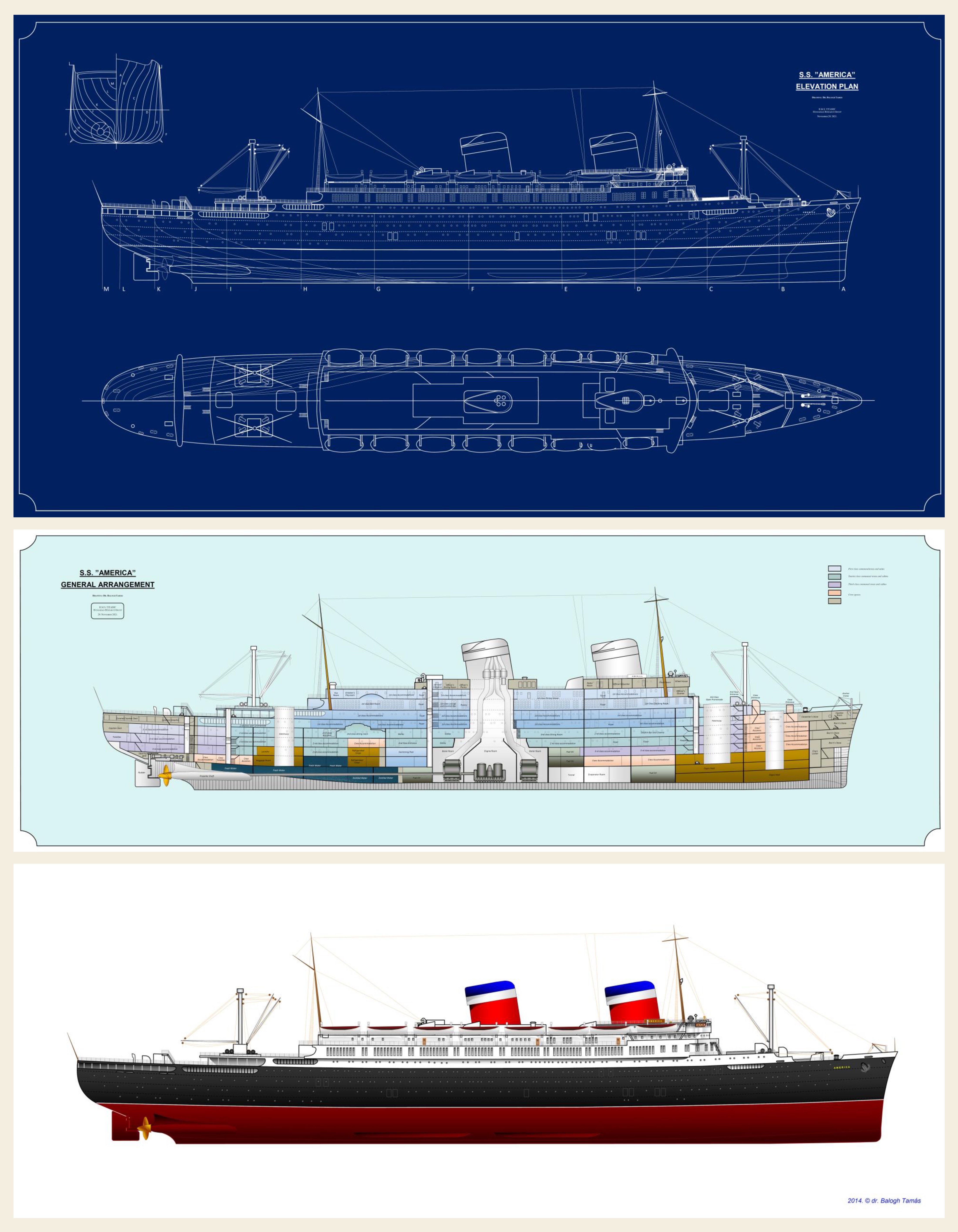
    Moreover, the ships of the OLYMPIC-class were not only unique among their four-funelled contemporaries in the use of dummy funnels: the famous German Ballin Trio, the three-funnelled ships of the IMPERATOR-class, also had a dummy funnel at the rear. This was the case with the sister ships CAP POLONIO and CAP TRAFFALGAR of the Hamburg-Süd Line, or the STRATHNAVER of the Peninsular and Orient Line (P&O), the ILE de FRANCE and NORMANDIE of the CGT, the EMPRESS of BRITAIN of the Canadian Pacific Line, or BRITANNIC (III.) of the WSL and AMERICA of the US Lines, and we could continue. What's more! In case of Cunard Line's two-stacker sister ships of ANDRIA and ALSATIA in the 1950s (!), the first funnel was a dummy funnel as well. This means that then - even after the design-revolution, the constructivism, and the functionalism - it was a common feeling that to seem bigger, is better.

    035.jpg

    Fig. 47.: On ships in the IMPERATOR-class, the rear funnel (although the ships had “only” three funnels) was also a dummy. (Source: Dr. Tamás Balogh)


    036_1.jpg

    Fig. 48.: And when there are already just two funnels, but they are also too many: AMERICA and its dummy-funnel (this time the first). (Source: Dr. Tamás Balogh)


    037038.jpg

    Figs. 49. and 50.: BRITANNIC (III.) above and her sister GEORGIC (below). GEORGIC originally also had two funnels, but it was converted to a single-stacker by removing the forward dummy-funnel in World War II. (Source: Wikipedia)


    So, using parts (by neglect of material- and cost-saving) which were completely unnecessary for technical reasons, just for the sake of appearance (purely for design, or optical purposes), was a common thing for a long time.

    Perhaps one of the most extraordinary of these items was the third funnel of the NORMANDIE, which, however, was not a completely inoperable piece: the kennel for the dogs of the passengers were placed in it. The dog kennel was a place surrounded by stainless steel bars, in the middle of which was an drinking fountain for the animals in an oval space. The kennels were steam-heated, ventilated rooms with fresh litter and straw waiting for the animals daily. Allowed daily exercise for the dogs was provided on the upper deck around the funnel base. Of course, rescue equipment was also provided for the dogs in puppy, large and medium sizes, and a special daily menu was printed in French (offering a variety of bones, soups, biscuits and vegetables). A separate veterinarian was also available on board if required.

    037_1.jpg

    Figs. 51.: Dog Kennels, located inside the third - dummy - funnel of NORMANDIE (Source: Popular Mechanics, August, 1939.)


    IV.) Under the spell of funnels:

    Designer of the GREAT EASTERN,the  French-born British engineer genius Isambard Kingdom Brunnel once responded to accusations connected to his liner-plans (according to that building a ship of such a huge size is uneconomical and unnecessary) that “the bigger is better”.

    His idea hadn't been approved for nearly 40 years, but now we know that he was right. He is not wanted that his ships won the title of the largest sea-going steamers for selfish purposes. These ships had been built so big only for they could take on board the amount of coal needed to cross the ocean without refueling. They had to be large in the first place, and many passengers had to be accommodated to make their journeys profitable.

    Incidentally, the large size was accompanied by stability, seaworthiness, which was of great value to passengers who wanted to cross safely (even if, as is well known, all pioneers had a hard time, so the handling of Brunnel’s vast and unprecedented ocean liners was not an easy task either, and the necessarily untrained crew certainly caused many accidents).

    Still, the “mania for size” brought to life by talented or just untalented engineers trying to follow Brunnel, continues to this day. An interesting side effect of this was the attraction to multi-funnelled ocean-going vessels, as the epitome of safety, speed and power, which was initially embodied in the construction of the four-stackers, but we also know of a case where designers flirted with the idea of installing even more funnels…

    The following are manifestations of this strange mania for size (presenting three unrealized oceanliner plans, which were partly intended as a joke):

    038.jpg

    Figs. 52.: Concept of Jochann Schütte for the KAISER WILHELM II. in 1902. (Source: Pinterest)


    The success of the first fourstacker oceanliners (the KAISER WILHELM der GROSSE and its sistership, KRONPRINZ WILHELM, and the rival DEUTSCHLAND) prompted the shipping company Norddeutscher Lloyd, to build new, larger and faster ones.

    Answering the order of the company, in 1900, several designers prepared a design proposal for the new ships (later KAISER WILHELM II and its sister ship, KRONPRINZESSIN CECILIE). Jochann Schütte's project to upgrading the KAISER-class stood out from the rest by he had now installed even five (!) funnels on the upper deck, instead of the previous four.

    His plans contained nothing new in other respects, only in that the German engineer gave the hull of his ship the shape of the warships, more precisely the stern of the cruisers - perhaps as a result of the universal interest in warship-building (which was booming at the time and was also of great concern to the public, and the patriotic sentiments centered around it).

    This is all the more remarkable because the so-called cruiser-stern began to spread on ocean liners only about ten years later, but only gained popularity in the 1930s following the success of the largest liner built with cruiser stern, the QUEEN MARY.

    039a.jpg

    Figs. 53.: Concept of William Francis Gibbs for the INDPENDENCE in 1915. (Source: The New York Times, August 3. 1919.)


    The background of this situation is well highlighted by the third example is a funny mirror in front of all car-crazy people, which is nothing more than a caricature made by a German photographer in the 1920s as a prank for April 1st. Using a picture of VATERLAND (US-owned LEVIATHAN) confiscated from the Germans, he created a photomontage of a ten-funnelled limousine oceanliner – the imaginary PRESIDENT ROOSEVELT – as a reference to the contemporary enthusiasm for vast dimensions.


    040_2.jpg

    Figs. 54.: The German caricature-photo. (Source)


    Sources:

    http://magnificenttitanic.tumblr.com/page/32

    http://www.copperas.com/titanic/boiler.htm

    http://www.titanic-theshipmagnificent.com/synopsis/chapter15/

    http://de.academic.ru/dic.nsf/technik/19532/Schiffskessel

    http://www.sterling.rmplc.co.uk/visions/pwrtr.html

    http://www.oshermaps.org/search/zoom.php?no=2001046.0003#img2

    http://wesworld.jk-clan.de/thread.php?postid=102467

    https://fbcdn-sphotos-b-a.akamaihd.net/hphotos-ak-prn2/1377371_741929022491100_634000637_n.jpg


    It would be great if you like the article shared. If you are interested in the works of the author, you can find more information about the author and his work on the Encyclopedia of Ocean Liners Fb-page.


    009_logo_jndigo_blue.jpg

  • Tagtársunk tárlata

    Tags: tit_hajózástörténeti_modellező_és_hagyományőrző_egyesület, tit_hmhe, hajómodellező_tagozat, TIT, susányi_oszkár

    Susányi Oszkár, egyesületünk tagja - többszörösen elismert hajómodellező mester, akinek különös műgonddal készült alkotásai lakhelye, Gyál község helyi értéktárába is bekerültek - alkotásaiból nyílik kiállítás 2022. március 18-án pénteken, 18:00 órai kezdettel, amelyre minden érdeklődőt szeretettel várunk.

    meghivo_5.jpg

    Az egyesültünk érintettségével megvalósuló 2022. évi első kiállításon az alkotó 5 hajómodellje, Leonardo da Vinci alkotásait bemutató 15 makettje és 5 ágyúmakettje lesz megtekinthető.

    További információk az alkotóról: itt

    A modellező mester honlapja és alkotásai: itt

  • S.S. KAISERIN ELISABETH, 1912-1920 – Az Austro-Americana befejezetlen óriásgőzöse

    Tags: tit, balogh_tamás, tit_hajózástörténeti_modellező_és_hagyományőrző_egyesület, tit_hmhe, hajózástörténeti_tagozat, Óceánjárók, Encyclopedia_of_ocean_liners

    Az első világháború Európa-szerte több tervbe vett vagy építeni kezdett nagy óceánjáró személyszállító hajó építését késleltette, vagy épp hiúsította meg végleg. Az Austro-Americana – Ausztria-Magyarország transzatlanti járatokat fenntartó egyik legnagyobb hajótársasága – építés alatt álló óriásgőzösén szintén felfüggesztették a munkálatokat, s a frontvonalon fekvő trieszti Monfalcone Hajógyárban épülő hajó végül a kibontakozó hadműveletek egyik „áldozatává” vált. Vajon milyen hajó lett volna? Mi indokolta a Monarchia számára egy, az országban addig ismeretlen nagyságú utasszállító hajó felépítését, s mi okozta a végzetét? E tanulmány ezekre a kérdésekre válaszol.


    I.) Előzmények – Az Austro-Americana születése:

    Az osztrák (1867-1918 között osztrák-magyar) tengerhajózás favoritja az 1833-as alapítású Osztrák Lloyd (Österreichischen Lloyd) hajótársaság volt, amely az első világháború kitörésekor, 1914-ben összesen 65 hajóval, 235 000 BRT térfogattal és több, mint 6 000 alkalmazottal rendelkező vállalatként az ország legnagyobb kereskedelmi tengerhajózási vállalata volt. Az Adriai-tenger (az Atlanti-óceán melléktengerének számító Földközi-tenger melléktengere) északi partján elterülő osztrák (-magyar) birodalomban sokáig nem akadt vetélytársa.

    A birodalom tengerészei jószerével csak helyi és mediterrán hajózást bonyolítottak, azt is jellemzően vitorlás hajókkal. A lussipiccolói (ma: Mali Losinj, Horvátország) Cosulich család tagjai – Antonio Felice Cosulich és fiai, Castillo és Alberto – azonban a XIX. század utolsó harmadában felismerték, hogy a gőzhajózásé a jövő, és a legfőbb osztrák kikötőben, az akkor Ausztria-Magyarország fennhatósága alá tartozó olaszországi Trieszt kikötővárosában, Cosulich Hajózási Társaság (Cosulich Società Triestina di Navigazione) néven gőzhajózási társaságot alapítottak 1895-ben.

    Ugyanebben az évben – 1895-ben – alapította meg Gottfried August Schenker osztrák fuvarozó és William Burell skót szállítmányozási kereskedő is a saját gőzhajózási társaságát Osztrák-Amerikai Hajózási Társaság (Austro-American Shipping Co., vagy Compagnia di Navigazione Austro-Americana) néven, azzal a céllal, hogy az osztrák ipar ellátását függetlenítse a drága német, s a megbízhatatlan olasz kikötőktől, és árufuvarozási vonalat hozzon létre Ausztria és Észak-Amerika között az osztrák textil- és pamutipar nyersanyagellátására. A cég székhelye szintén Triesztben volt.

    Az 1901-1902-es gazdasági válságot kihasználva a Cosulich testvérek megszerezték Burell tulajdonrészét és 1902-ben bevásárolták magukat az Austro-Americana-ba, amelyet ettől kezdve Schenker, Cosulich und Co., Austro-Americana néven ismertek. Alberto Cosulich ugyanekkor hajógyárat létesített a Trieszt melletti Monfalconéban (Cantiere Navale Triestino – CNT). Egy évvel később a Cosulich-testvérek a meglévő 14 áruszállító gőzhajójukat is a közös vállalkozásba apportálták, amelynek neve ekkor „Vereinigte österreichische Schiffahrtsgesellschaften der Austro-Americana und der Gebrüder Cosulich”-ra változott (olaszul: Unione Austriaca di navigatione Austro Americana e Fratelli Cosulich Societá anonima), tehát már a Schenker név is kimaradt a cégnévből. A társaság 19 hajója a Trieszt-Messina-Nápoly-Palermó-New York útvonalon közlekedett, s a vállalat 1904-ben bekapcsolódott a transzatlanti személyszállításba.

    Az Osztrák-Magyar Monarchiából kiinduló transzatlanti kivándorlás hosszú ideig a német Norddeutscher Lloyd, illetve a Hamburg America Line kezében volt, ám 1902-ben a brit Cunard Line megállapodott a magyar kormánnyal a kivándorló magyar állampolgárok Fiumén keresztül történő kiszállításáról, s a koncesszió 1903-ban az osztrák alattvaló kivándorlókkal bővült. (A Cunard nyereségéből valamennyi „visszacsorgott” a magyar hajózási vállalatoknak, ezért cserébe önként lemondtak a konkurenciáról. (A ma is legismertebb, Fiuméből induló Cunard-hajó a TITANIC-tragédia túlélőit mentő CARPATHIA gőzös volt).

    001_27.jpg

    1. ábra: Az osztrák és a magyar kereskedelmi tengerhajózási társaságok hajóinak útvonalai 1833-1918. Az Austro-Americana elsősorban az észak- és dél-amerikai kontinensre, az Osztrák Lloyd Afrikába, illetve a Közel- és a Távol-Keletre, a magyar hajótársaságok pedig jellemzően a Fekete-, az Égei- és a Földközi-tenger kikötőibe közlekedtek (készítette: Dr. Balogh Tamás).


    A hazai hajótársaságok közül a trieszti Cosulich-testvérek által alapított Austro-Americana azonban másként reagált, amikor úgy döntött, hogy nem engedi át az egész kivándorlási üzletet az angoloknak. 1904. június 9-én útnak indította New Yorkba a vállalat GERTY gőzösét, 314 emigránssal a fedélzeten. A német társaságok helyeselték az osztrák „kiállást” (ha már saját hajóik kiestek ebből a versenyből) és megnyitották az osztrákok számára az „Atlantic Pool”-t, a kivándorlókat szállító hajóstársaságok árkartelljét, aminek meg is lett a hatása: az Austro-Americana áru-, és személyforgalma megugrott.

    1907-ben megindultak a járatok New Orleansba és Dél-Amerikába (a New Orleans-i útvonal 1908-ban megszűnt), 1913-ban pedig megállapodás született a Canadian Pacific hajótársasággal is arról, hogy alternatív járatokat biztosítanak Triesztből Kanadába, ám ezt végül nem találták gazdaságosnak és 6 út után (még 1913-ban) a szolgáltatás folytatásának leállításáról döntöttek. A társaság hajói 1904-ben még csak 4 224 személyt és 2 172 tonna árut szállítottak, 1912-ben viszont már 101 670 utast és 10 133 tonna árut (vagyis a társaság hajóin szállított utasok száma rövid 8 év alatt a huszonnégyszeresére, az áruforgalom pedig több mint a négyszeresére nőtt). A társaság hajóparkja 1914-ben 28 egységet számlált, s az Ausztria-Magyarországra irányuló összes tengeri áruszállítás közel 17 %-át (a Dél-Amerikából érkező áruknak viszont a 95 %-át) bonyolították.

    Ehhez persze új, modern, nagyméretű személyszállító hajók kellettek és természetesen további tőke, amelyet részben az osztrák kormánytámogatás (1903-ban 1,53 millió korona) biztosított (jóval csekélyebb értékben, mint az ugyanebben az évben 10 millió koronával dotált Osztrák Lloyd esetében). Ennek következtében 1911-ben már 1,5 millió korona nyereséget osztottak szét a részvénytulajdonosok között. Nem véletlen, hogy ez a társaság építette fel a legnagyobb osztrák-magyar transzatlanti óceánjárókat. 1905-ben épült Triesztben az osztrák-magyar trónörökös feleségéről elnevezett 5 491 tonnás SOFIE HOHENBERG, 1908-ban Glasgow-ban az első amerikai elnök feleségéről elnevezett 8 312 tonnás MARTHA WASHINGTON, 1911-ben Triesztben pedig a kettős monarchia uralkodója, a császár és király nevét viselő 12 568 tonnás KAISER FRANZ JOSEF I., az Austro-Americana legnagyobb (vízre bocsátott) gőzöse, egyben a Monarchia legnagyobb kereskedelmi hajója.

    Az Austro-Americana sikere nyomán 1912-ben a társaság Monfalcone-i hajóépítő telepén hozzáláttak egy még nagyobb hajó, a KAISERIN ELISABETH építéséhez, amely az 1914-ben kitört világháború miatt azonban végül is soha sem készülhetett el. Pedig – ha felépül – ez az óceánjáró lett volna a valaha épített legnagyobb osztrák-magyar hajó…

    002_24.jpg

    2. ábra: Az Austro-Americana óceánjáró utasszállító-sorozata: a mintaként szolgált, a Russel & Co. Hajógyárban, Glasgowban rendelt MARTHA WASHINGTON (fent) és az annak alapján, de immár saját tervezés eredményeként és hazai hajógyárban, Monfalconéban felépített KAISER FRANZ JOSEF I. jellegrajzai és KAISERIN ELISABETH jellegrajzának rekonstrukciójára tett 2015. évi első kísérlet (készítette: Dr. Balogh Tamás).


    II.) A KAISERIN ELISABETH építése és bontása:

    Az addigi legnagyobb osztrák-magyar óceánjáró, a KASIER FRANZ JOSEF I. építése még nem érkezett a végéhez, amikor a tulajdonos hajózási társaság és az építő, a Trieszt melletti monfalcone-i hajógyár megkezdte az előtanulmányokat, majd a tervek készítését a második egység, a nagyobb és gyorsabb KAISERIN ELISABETH felépítéséhez, amelyet ugyanazon a vonalon (az Európa és az Észak-Amerika közötti úton) terveztek szolgálatba állítani.

    A KAISERIN ELISABETH terveit a társaság legutóbbi hajói, a MARTHA WASHINGTON és a KAISER FRANZ JOSEF I. tervei alapján készítették el:

    003a.png

    003c.jpg

    3. és 4. ábra: Az Austro-Americana hajóinak szülőhelye, a Cantiere Navale Triestino Monfalconéban. A hajógyár délkeleti részén 7, az újonnan kiépült északnyugati részen további 3 sólyatér állt rendelkezésre a különböző méretű hajók építéséhez. A legnagyobb hajókat a leghosszabb és legszélesebb (a 2-es és a 3-as számú) csúsztatón építették. Az alsó kép a hajógyárról 1914-ben készült terepasztalt mutatja, amelyen balra – az úszódokkba emelve – a KAISERIN ELISABETH makettje látható (forrás:  Consorzio Culturale Monfalconese, Museo del Mare, Trieste).


    Vízvonalhossz:                  164,59 m

    Teljes hossz:                      175,0 m

    Szélesség:                          20,65 m

    Merülés:                             13,18 m

    Térfogat:                             14 700 BRT

    Sebesség:                           19,5 csomó (36,1 km / h)

    Befogadóképesség:            2 000 utas


    Amikor a frissen átadott KAISER FRANZ JOSEF I. működésének első hónapjai egyértelműen kedvező tapasztalatokat biztosítottak, a cég menedzsmentje az új hajó építésének gyorsítását sürgette.

    Az építési folyamat és a háború jelentette kényszerű leállás, majd a csaknem teljesen elkészült hajótest háború utáni bontásának kronológiája a következő:

    1912. november 30.: Az utasszállító gerincfektetése Monfalconéban 39-es gyártmányszámmal (több szerző szerint a hajógyárban készült első nagy óceánjáró a CONTE GRANDE volt 1927-ben, a valóság ezzel szemben az, hogy a KASIERIN ELISABETH volt a hajógyár egyik első ilyen gyártmánya).

    1914. október 14.: Az építés előrehaladott szakaszában megsérül egy építőmunkás. A háború kitörése miatt az építkezést felfüggesztik. A gyár ekkor bérelt eszközökkel a DDSG budapesti telephelyén (az óbudai hajógyárban) és a polai Azrenálban folytatja a termelést (zömmel katonai megrendelések teljesítését, többek között az U-27 osztályú tengeralattjárók gyártását a flotta számára)

    1915. május: Az olasz hadba lépést követő harcok során a front többször áthalad a monfalconei hajógyár telephelyén, s a sólyán álló befejezetlen hajótest a harcokban több ízben megsérül (több tüzérségi találat éri, a belsejében tűz üt ki).

    1915. július: Az 1915. június 23-án az isonzói fronton megindult olasz offenzíva – a kellő előkészítés hiányosságai és a terepviszonyok teljes figyelmen kívül hagyása miatt – július elejére elakad, s a Monarchia hadserege július 18-án nagyszabású ellentámadást indít. A hadműveletek egyik „áldozata” a frontvonalon fekvő hajógyárban álló KASIERIN ELISABETH. A gyár területe még az első olasz támadással került olasz katonai ellenőrzés alá június 9-én. A július 7-én elakadt olasz támadásra válaszul már másnap – július 8-án – megkezdődik az osztrák-magyar ellentámadást bevezető tüzérségi előkészítés, aminek az egész hajógyár, s a sólyán álló óceánjáró is kárát látja. Az építés előrehaladott szakaszában álló 15 000 tonnás óriást a középső felépítmény alsó fedélzetének magasságáig több olasz gyújtógránát is eltalálja, amelyek nyomán katasztrofális tüzek törnek ki a hajótest belsejében, amelyet az olasz tüzérség ezt követő bombázása tovább rongál.

    1915. október: A Monfalcone irányába előretörő osztrák-magyar hadsereg tüzérségi bombázása károsítja a kiégett hajótestet, amelynek oltása a két front között, a senki földjén gyakorlatilag lehetetlen.

    1917. október: A caporettó-i áttörés (az olasz front 1917. október 24-én történt összeomlása) után az osztrák-magyar csapatok visszafoglalják a hajógyárat és a dokkokat. A Cosulich család kárpótlásért fordul a császári és királyi kormányhoz a hadműveletek miatt a gyárat ért károk kompenzálására és a termelés újraindítására. Egy ideig (amíg meg nem történik a teljes kárfelmérés) a hajót ért károk kijavítását és az építési munkálatok folytatását tervezik. A hajó nevét ekkor (a hajógyár visszafoglalását lehetővé tevő győztes csaták helyszíne után) ISONZO-ra változtatják. Az alapos elemzés azonban feltárja, hogy a hajón nincs mit helyreállítani, a tűzvonalban fekvő óriást az egymást követő tüzérségi lövésváltások olyan súlyosan megrongálták, hogy a kijavítása lehetetlen.

    1918. november: Bár a padovai fegyverszünet (1918. november 3.) szerint a monfalconei hajógyár területe a Monarchiánál marad, a háború elvesztése és az Osztrák-Magyar Monarchia szétesése végleg meghiúsítja a hatalmas hajó maradványainak hasznosítását. Az addig elkészült részeket Trieszt olasz megszállását követően ezért lebontják.

    1920.október: A félkész hajó utolsó szerkezeti elemeinek eltávolítása.

    005_12.jpg

    5. ábra: Az Austro-Americana megrendelésére építeni kezdett két óceánjáró a hajógyárba északnyugat felől érkező olasz haditudósítók fotóján 1915. június 9-én. A jobb oldali hajó a KAISERIN ELISABETH.

    006_7.jpg

    6. ábra: A hajó tatjáról készült közelképen tisztán kivehető a kormánylapát és a baloldali hajócsavar, valamint a tatfelépítmény és az alatta lévő, a farkosárban kialakított nyitott sétafedélzet. Előrébb a középső felépítmény alsó, végig nyitott (mellvédes) sétánya, s felette a felső sétafedélzet látható (a kép bal szélén az elülső, zárt rész mellvédjével). (Forrás: Atlante / Dizionario del 1915 in Friuli Venezia Giulia)

    007_8.jpg

    7. ábra: A kényszerűen félbehagyott óceánjárók és az építésükhöz élükre állítva és egymáshoz támasztva felhalmozott, az ökörszemablakok számára perforált oldallemezek (a kép előterében). (Forrás: Associazione Marinara Aldebaran, Trieste)

    008_9.jpg

    8. ábra: A KAISERIN ELISABETH-nek a támadás kezdetén az olasz állások felé néző bal oldala. Jól megfigyelhető a középső felépítmény és két sétafedélzete: az alsó (teljes hosszában nyitott, tömör lemezmellvédes) sétány és a felső, csak az elülső felén mellvédes sétány. A fedélzeten elöl az első kémény füstaknája, hátrébb pedig a gépakna négyszögletes szerkezete látható.

    009_6.jpg

    9. ábra: A hajótestből füst száll fel, egyes nyílások felett korom és égésnyomok. A tüzérségi támadásban megsérült hajó „olasz oldala” 18915 júniusában. Jól láthatók a középső felépítmény sétafedélzetei: az alsó, teljes hosszában nyitott és tömör lemezmellvéddel ellátott alsó és a felső – lemezmellvéddel csak az első felén rendelkező – sétány. (Forrás: Associazione Marinara Aldebaran, Trieste)

    010_3_1.jpg

    10. ábra: A hajó osztrák-magyar hadállások felőli jobb oldala. A hajóorr felső ablaksora alatt elöl közvetlen tüzérségi találat nyoma. Az elszíneződött hajótesten mindenütt erős égés jelei. (Forrás: Wikimedia Commons)

    011_012_013.jpg

    11., 12. és 13. ábra: A No 39-es objektum a sólyapályán 1919-ben. A középső képen az előtérben olasz katonák beszélgetnek. Az óceánjáró mellett (a fa állványzat hálójában) egy eredetileg Kína számára építeni kezdett, majd a háború kitörésekor az osztrák-magyar haditengerészet számára lefoglalt cirkáló, amely a front átvonulása miatt szintén befejezetlen maradt. (Forrás: Associazione Marinara Aldebaran, Trieste)

    014_4.jpg

    14. ábra: A hajógyári telephely romjainak eltakarítása közben, 1920 elején készült a fenti kép, amikor a KAISERIN ELISABETH mellett építeni kezdett óceánjáró törzsét már szétbontották, s a helyén a daruzott új nagy csúsztatót építik (a képen épp a darupályát tartó vasbeton pilléreket zsaluzzák). Az óceánjáró törzsén – a vízvonal alatti részeken – rengeteg utólag vágott nyílás látható, amelyeken keresztül a bontók bejuthatnak a hajóba. A középső felépítmény két fedélzetét, a hátsó felépítményt és a mélyített orrfedélzet mellvédjeit már jól láthatóan lebontották. Ez az utolsó ismert kép a hajóról. (Forrás: Associazione Marinara Aldebaran, Trieste)


    III.) A hajó rekonstrukciója:

    A hajó tervei – jelenlegi ismereteink szerint – nem maradtak fenn. Az, amit a fő méreteken kívül a hajó megjelenéséről és általános elrendezéséről tudni lehet, mindössze néhány forráson alapul:

    1)  Az építés alatt álló, illetve a front átvonulása miatt megrongált hajótestről több fotográfia maradt fenn (5.-14. kép), amelyeket olaszországi levéltárak őriznek.

    2)  A hajó feltűnik a híres osztrák tengerészeti festő, Alex Kircher (1867-1939) trieszti kikötőt ábrázoló nagyméretű pannóján, amely ma Bécsben a Műszaki Múzeumban (Technisches Museum) látható (15.-16. kép).

    3)  Ezen kívül létezik a kikötőnek egy 1914-ben készült terepasztala (4. kép), amelynek alkotói elkészítették a hajó egy kis méretarányú makettjét is (17.-19. kép). A terepasztalt a Museo del Mare őrzi Triesztben.

    015_4.jpg

    016_1.jpg

    15. és 16. ábra: Alexander Kircher „Triester Hafen” („A trieszti kikötő”) c. festménye 1918-ból (az előző oldalon lent) és annak a hajót ábrázoló részlete (fent).


    Mindezek a források együttesen tették lehetővé a hajó jellegrajzának rekonstrukcióját, amelyet most örömmel osztunk meg az érdeklődőkkel. A rekonstrukciót megnehezítette, hogy a három forrás (a korabeli festmény, az építési fotók és a korabeli terepasztalhoz tartozó makett) eltérő módon ábrázol bizonyos részleteket. Ezek közül a fényképeket fogadtuk el hitelesnek, a korabeli kisméretű makettet és a festményt, csak ott használtuk, ahol a rajtuk látható részletek hitelességéhez nem fér kétség.

    A fentiekre tekintettel a hajó általános elrendezéséről nagy biztonsággal megállapíthatók a következők: a 175 méter hosszú hajó jól tervezett, három, harmonikus elrendezésű felépítménnyel (egy ott- egy tat- és egy középső felépítménnyel) rendelkező, háromkéményes, kétárbocos, két hajócsavaros hajó lett volna, hagyományos (dugattyús gőzgépes) meghajtással.

    017_018_019.jpg

    17., 18. és 19. ábra: A Cantiere Navale Triestino hajógyár monfalconei telephelyének terepasztala a hajó makettjével. (Forrás: Wikipedia, Pinterest)


    A korabeli ábrázolások a felépítmények sétafedélzetei és a parancsnoki híd kialakítása tekintetében tartalmazták a legtöbb eltérést.


    1)  A hajógyári terepasztalhoz tartozó makett (amely annyira kicsi, hogy még a hajótest oldalán lévő beszálló-ajtókat sem dolgozták ki rajta) a középső felépítményen két sétafedélzetet mutat, amelyek közül az alsó teljes hosszában nyitott, míg a felette lévő az elülső végén üvegezett és a hátsó felén nyitott sétány. A két sétafedélzet elülső felén tömör lemez-mellvéd, a hátsó felén pedig csak korlátok védik az utasokat (de a lemez mellvéddel ellátott rész a felső sétafedélzeten hosszabb).

    Az orrfelépítményt mélyített fedélzet választja el a középső felépítménytől. A mélyített orr-fedélzeten áll az előárboc és az elülső rakterek egyik raktárnyílása (amelynek a párja az előárboc előtt, az emelt orrfedélzeten kapott helyet).

    A makett szerint a hajó tat-részén szintén két sétafedélzetet alakítottak ki: a hajótestben egy lemezmellvéddel védett nyitott sétányt (amely körbefut a hajótest lekerekített tatján a farkosár felett), s egy végig nyitott – csupán korláttal védett – sétányt az előbbi sétány feletti fedélzeten álló tatfelépítmény hátsó felének két oldalán egy-egy rövid szakaszon (a sétány teteje a felépítményen elhelyezett mentőcsónakok vízrebocsátását szolgáló platform).

    A tatfelépítményt a középső felépítménytől elválasztó nyitott fedélzetrészen a hátsó rakterekbe vezető raktárnyílást helyezték el. A főárboc a tatfelépítmény első felének közepén áll.

    A parancsnoki híd a középső felépítmény tetejét alkotó csónakfedélzet elején, az elülső mellvédtől hátrébb húzott (körüljárhatóan kialakított) tiszti lakosztályokat befogadó fedélzeti ház tetején kapott helyet, annak elülső falától jelentősen hátrébb húzva. A parancsnoki híd szárnyai végig nyitottak.


    2)  A Kircher-festményen ezzel szemben a középső felépítmény mindkét sétányának az elülső része üvegezett (az alsó hosszabban) és teljes hosszában tömör lemezmellvéddel védett.

    Az emelt orrfelépítményt a középső felépítménytől elválasztó mélyített orrfedélzet két oldalán egy-egy, a mellvédekhez csatlakozó fedélzeti ház kapott helyet a tetején mentőcsónakkal.

    Tatfelépítmény nem látható. A festményen csupán egy, a mélyített orrfedélzetihez hasonló fedélzeti ház tűnik fel, a tetején mentőcsónakkal. A hajótestben a farkosár felett körbefutó nyitott sétány hiányzik.

    A csónakfedélzet elülső végén (a tiszti lakosztályok szélességében, azok elülső fala és a csónakfedélzet elülső mellvédje között) egy üvegezett folyosó húzódik, amelyen keresztül az utasok közlekedhetnek a csónakfedélzet két oldala között. Ez egyben szélvédett kilátóhelyként is szolgál a számukra a nyílt óceánon.

    A parancsnoki híd közepén álló kormányház elülső falának függőleges síkja egybeesik a csónakfedélzet elülső mellvédjének síkjával.

    A parancsnoki híd két szárnyának végén egy-egy üvegezett navigációs fülke áll.


    3)  A fényképek a fentiektől több ponton eltérő elrendezést mutatnak. Igaz ugyan, hogy a középső felépítménynek egymás felett két sétafedélzete van, de az alsó – teljes hosszában nyitott – sétány végig tömör lemez mellvéddel védett. Korlátok csak a felső sétány hátsó, nyitott felén találhatók (a felső sétány elülső, üvegezett részén lemez mellvéd van).

    A parancsnoki híd és a kormányház építése a felvételek készítésekor még nem történt meg, de a középső felépítmény felső fedélzetén (a csónakfedélzeten) található elülső mellvéd kialakítása alapján valószínűsíthető, hogy a Kircher-festményen látható megoldás helyett inkább a hajógyári terepasztal makettjén látható megoldást kívánták alkalmazni.

    020.jpg

    20., 21. és 22. ábra: A Kircher-festmény (fent), a gyári makett (középen) és a fotók (lent) alapján látott általános elrendezés (készítette: Dr. Balogh Tamás).

    021.jpg

    23. ábra: A hajónak az előkerült fényképek alapján pontosított rekonstrukciója (készítette: Dr. Balogh Tamás).


    Epilógus:

    A KAISERIN ELISABETH a gerincfektetése idején – 1912-ben – a legnagyobb óceánjáró volt, amelyet addig a Földközi-tenger medencéjében építeni kezdtek. Elsőbbsége azonban nem tartott volna sokáig, akkor sem, ha nem tör ki a világháború és a hajó építése befejeződik, s megkezdi a menetrend szerinti járatait. Az 1913-1914 folyamán szolgálatba állított három GALLIA-osztályú francia óceánjáró (a GALLIA, a LUTETIA és a MASSILIA) egy kicsivel felülmúlta a méreteit (a hosszuk 182 m, a térfogatuk 14 966 tonna volt), az 1916-ban építeni kezdett két új olasz óceánjáró, a DUILIO és a GIULIO CESARE – bár e hajók csak a háború után, 1923-ban és 1926-ban készültek el – pedig már egyértelműen felülmúlta (a hosszuk 194 m, a térfogatuk 25 000 tonna volt).

    Az Osztrák-Magyar Monarchia legnagyobb kereskedelmi hajója számára a legkülönösebb rivális mégsem Franciaországból, vagy Olaszországból, hanem Németországból érkezett, amikor a jövedelmező észak-atlanti hajójáratokat üzemeltető német H.A.P.AG hajózási társaság két új óceánjárót rendelt az 1913-ban általa megvásárolt, 1897-ben Ligure Brasiliana néven alapított olasz hajózási társaság, az 1914-től Transatlantica Italiana Societa Anonima di Navigazione számára: egyet az észak-atlanti, egyet pedig a dél-atlanti utakra, hogy olasz kikötőkből kiindulva és olasz lobogó alatt közlekedjenek. Az ANDREA DORIA néven szolgálatba állítani tervezett észak-atlanti gőzös és testvére, a CONTE di CAVOUR hossza 237 m, térfogata 37 000 tonna lett volna, míg a déli Atlanti-óceánra szánt kisebb társuk épp a KAISERIN ELISABETH méretkategóriájába tartozott volna, a hossza 175,4 m, térfogata 18 500 tonna lett volna.


    022_1.jpg

    023_1.jpg

    24. ábra: A KAISERIN ELISABETH és a TITANIC összehasonlítása (fent). Az 1910-es évek mediterrán óceánjáróinak felső méretkategóriája az 1890-es évek legnagyobb atlanti óceánjáróinak méretét idézte. A KAISERIN ELISABETH hossza az 1881-es építésű s.s. CITY of ROME (171 m), térfogata pedig az 1895-ben vízrebocsátott s.s. CAMPANIA (13 000 tonna) méretének felelt meg (készítette: Dr. Balogh Tamás).

    25. ábra: A KAISERIN ELISABETH általános elrendezése (lent) (készítette: Dr. Balogh Tamás).


    024_1.jpg

    26 ábra: A KAISERIN ELISABETH, s francia és olasz riválisai (készítette: Dr. Balogh Tamás).


    E hajók építése azonban szintén meghiúsult: azután, hogy Olaszország 1915-ben korábbi szövetségesei, Németország és Ausztria-Magyarország ellen lépett be az első világháborúba, olasz igazgatóság alakult, s a cég összes német tulajdonú részvényét megvásárolták, egy évvel később pedig eladták az irányítási jogot az Ansaldo-csoportnak. A vállalatot 1934-ben felszámolták. A tervezett nagy hajókat sohasem építették fel. A háború után a Cosulich testvérek is újjáalakították vállalkozásukat. az Austro-Americana az immár olasz fennhatóságú Triesztben a testvérek nevén, mint Cosulich Line működött tovább, 1937-ig, amikor beolvadt az új, egységes olasz nemzeti hajótársaságba, s az Italia Societa Anonima di Navigazione keretében működött tovább. A háború utáni első nagy óceánjáróikat Monfalconéban építtették fel SATURNIA és VULCANIA néven 1925-ben és 1926-ban (a hajók hossza 200 m, térfogata 24 000 tonna volt).

    025_1.jpg

    27. ábra: A KAISERIN ELISABETH tervezett német riválisai (készítette: Dr. Balogh Tamás).


    Források:

    A Monarchia luxusgőzöseiről:

    https://hajosnep.hu/Media/Default/hu-HU/tevekenyseg/hirlevelek/2010/2010-evfolyam-2-szam.pdf?fbclid=IwAR266rxunAvYFE3VPn-aS61xG0EJyvkgpZ2ZTy1KhePHcTKC4yWQ5ZCTwj8

    A bemutatott fényképekről:

    http://www.studistorici.com/2012/12/29/carnemolla_numero_12-sala-b/?fbclid=IwAR0t2bW-pxVxRLyW-3hWkVJ6ChHkyGrGsGxuABX-qmVLeUi5Y_yekVWKMx0

    A hajó történetéről:

    http://www.archeologiaindustriale.it/sez_produzione_it...

    Egyéb források:

    https://www.facebook.com/piccolomuseotrieste/photos/a.613516462153412/1068713976633656

    http://www.atlantegrandeguerra.it/portfolio/monfalcone/

    http://www.atlantegrandeguerra.it/wp-content/uploads/2016/05/4a-MonfalconeCCM-1.jpg

    https://journals.openedition.org/diacronie/2594

    https://it.wikipedia.org/wiki/Cantiere_Navale_Triestino

    https://www.wrecksite.eu/imgBrowser.aspx?11388

    https://www.wikiwand.com/it/Cantiere_Navale_Triestino

    https://en.wikipedia.org/wiki/Number_64-class_cruiser

    https://www.google.com/search?q=Cantiere+Navale+Triestino+Monfalcone+1915&tbm=isch&ved=2ahUKEwjis5CJuaX1AhXJ34UKHUiqA0QQ2-cCegQIABAA&oq=Cantiere+Navale+Triestino+Monfalcone+1915&gs_lcp=CgNpbWcQA1DXB1i7a2CLbWgAcAB4A4ABgQGIAeoIkgEDMy43mAEAoAEBqgELZ3dzLXdpei1pbWfAAQE&sclient=img&ei=Gj3bYeK-OMm_lwTI1I6gBA&bih=568&biw=1366#imgrc=g83s9aAyWX2XdM

    https://www.facebook.com/page/167321909959726/search/?q=Kaiserin%20Elisabeth

    https://www.theshipslist.com/ships/lines/cosulich.shtml

    https://www.theshipslist.com/ships/lines/transitaliana.shtml

    https://earlofcruise.blogspot.com/2017/07/history-austro-americana-austro-hungary.html

    https://earlofcruise.blogspot.com/2017/07/history-one-of-earliest-steam-ship.html

    https://earlofcruise.blogspot.com/2017/07/history-one-of-earliest-steam-ship_30.html

    https://www.austrianinformation.org/current-issue-summerfall-2013/austro-americana


    Nagyszerű, ha tetszik a cikk és a benne megosztott képek. Ha érdeklik a szerző munkái, az Encyclopedia of Ocean Liners Fb-oldalán találhat további információkat a szerzőről és munkásságáról.

    A képek megosztása esetén, a bejegyzésben mindig tüntesse fel az alkotó nevét. Köszönöm!
    009_logo_jndigo_blue.jpg

  • s.s. KAISERIN ELISABETH, 1912-1920 - The unfinished liner of the Austro-Americana

    Tags: balogh_tamás, tit_hajózástörténeti_modellező_és_hagyományőrző_egyesület, tit_hmhe, hajózástörténeti_tagozat, Isonzo, Trieszt, Triest, Trieste, TIT, Monfalcone, Ocean_liners, Kaiserin_Elisabeth, Cosulich, Austro-Americana, Encyclopedia_of_ocean_liners

    World War I delayed or completely thwarted the construction of several large ocean-going passenger ships planned or under construction across Europe. Work on the giant steamer under construction for Austro-Americana, one of Austria-Hungary's largest transatlantic shipping companies, was also suspended. The ship built in the Monfalcone Shipyard near Trieste, eventually became one of the "victims" of the unfolding military operations as the front line oscilled for several times through the shipyard. What kind of ship would it have been? What justified fot the Dual Monarchy the building a passenger ship of a hitherto unknown size in the country, and what caused its doom? This study answers these questions.


    I.) Background - Birth of Austro-Americana:

    The favorite of Austrian (Austro-Hungarian between 1867-1918) shipping was the Austrian Lloyd (Österreichischen Lloyd) shipping company, founded in 1833. At the outbreak of the First World War in 1914, it had a total of 65 ships with 235,000 GRT and more than 6,000 employees, so it was the largest merchant shipping company in the country. For a long time, it had no rivals in the Austro-Hungarian Empire on the northern shores of the Adriatic (the northernmost arm of the Mediterranean Sea).

    The seafarers of the empire, for the most part, carried only local and Mediterranean sailing, also typically with sailing ships. However, members of the Cosulich family in Lussipiccolo (today: Mali Losinj, Croatia) - Antonio Felice Cosulich and his sons Castillo and Alberto - recognized that the future is belonged to the steam shipping, and in 1895 was set up the Cosulich Shiping Line (Cosulich Società Triestina di Navigazione) in the main Austrian port of Trieste, which city was then under the jurisdiction of Austria-Hungary.

    In the same year, 1895, Austrian hauler Gottfried August Schenker and Scottish shipping merchant William Burell to establish the freight line of Austrian-American Shiping Co. (or Compagnia di Navigazione Austro-Americana) between Austria and North America, initially with an eye on supplying the Austrian textile and cotton industry, with the aim of decoupling the supply of Austrian industry from expensive German and unreliable Italian ports. The company was also headquartered in Trieste.

    Taking advantage of the economic crisis of 1901-1902, the Cosulich brothers acquired all shares of William Burell when he left the company and they became co-owners of the Austro-Americana in 1902, which henceforth had been known as Schenker, Cosulich und Co., Austro-Americana. At the same time, Alberto Cosulich set up a shipyard in Monfalcone (that was the Cantiere Navale Triestino - CNT) near Trieste. One year later, the Cosulich brothers also contributed their existing 14 cargo steamships to the joint venture, which was renamed as "Vereinigte österreichische Schiffahrtsgesellschaften der Austro-Americana und der Gebrüder Cosulich" (Italian: Unione Austriaca di navigation e Fratel-li Cosulich Societá anonima), so that the name Schenker was omitted from the company name. The company's 19 cargo ships sailed on the Trieste-Messina-Naples-Palermo-New York route, and in 1904 the company became involved in transatlantic passenger transport as well.

    Transatlantic emigration from the Austro-Hungarian Monarchy was for a long time in the hands of the German Norddeutscher Lloyd and the Hamburg America Line, but in 1902 the British Cunard Line agreed with the Hungarian government to expatriate Hungarian emigrants through the Hungarian port of Fiume (today Rijeka, Croatia), and the concession was extended in 1903 to Austrian subjects too. Some part of Cunard's profits "flowed back" to the Hungarian shipping companies, so in return they voluntarily gave up the competition. (The most well-known Cunard ship depart from Fiume, was the CARPATHIA steamer, rescuing the survivors of the TITANIC).

    001_27.jpg

    Fig. 1: Routes of the Austrian and Hungarian merchant shipping companies 1833-1918. Austro-Americana sailed primarily to the North and South American continents, the Austrian Lloyd to Africa and the Middle and Far East, and the Hungarian shipping companies typically sailed to the Black, Aegean and Mediterranean ports (created by : Dr. Tamás Balogh).


    However, Austro-Americana, founded by the Cosulich brothers in Trieste, reacted differently when it decided not to hand over the entire emigration business to the English. On June 9, 1904, the company's steamer GERTY set sail for New York, with 314 emigrants on board. The German companies endorsed the Austrian ‘standstill’ (if their own ships had already dropped out of this race) and opened the ‘Atlantic Pool’, a price cartel of shipping companies transporting emigrants to the line, which had it's own effect: the Austro-Americana's freight and passenger traffic soared.

    Voyages to New Orleans and South America began in 1907 (the New Orleans route was discontinued in 1908), and an agreement was reached with Canadian Pacific in 1913 to provide alternative routes from Trieste to Canada, but this was ultimately not found economical and after 6 trips (still in 1913) it was decided to stop continuing the service. In 1904, the company's ships carried only 4,224 people and 2,172 tons of cargo, but by 1912, there were already 101,670 passengers and 10,133 tons of cargo (that is, during only 8 years, the number of passengers increased in twenty-four times, and freight-traffic quadrupled). The company's fleet numbered 28 units in 1914, handling almost 17% of all maritime freight to Austria-Hungary (95% of goods from South America).

    This, of course, required new, modern, large passenger ships and, of course, additional capital, provided in part by Austrian government subsidies (1.53 million Kronen in 1903) much less than in the case of the Austrian Lloyd's of 10 million Kronen in the same year. As a result, as early as 1911, a profit of 1.5 million Kronen was distributed among the shareholders. It is no coincidence that this company built the largest Austro-Hungarian transatlantic ocean liners. The 5,491-tonne SOFIE HOHENBERG, named after the consort of the Austro-Hungarian heir to the throne, was built in Trieste in 1905. The 8,312-tonne MARTHA WASHINGTON, named after the wife of the first American president, was built in Glasgow in 1908. The 12,568-tonne KAISER FRANZ JOSEF I, named after the emperor and king of the Dual Monarchy was built in Trieste in 1911 as the largest (launched) steamer in Austro-Americana fleet and the largest merchant ship of the Country.

    Following the success of Austro-Americana, in 1912 the company's shipyard in Monfalcone began building an even larger ship, the KAISERIN ELISABETH, which, however, could never be completed due the outbreak of World War I. Yet, if built, this ocean liner would have been the largest Austro-Hungarian ship ever built…

    002_24.jpg

    Fig. 2: Liner-series of the Austro-Americana: Profile drawings of the, MARTHA WASHINGTON (above) which was built as a model at Russel & Co. Shipyard in Glasgow; the KAISER FRANZ JOSEF I. (in the middle) which was built on the basis of the plans of the previous, but as a result of own design of the Monfalcone-shipyard; and finally the KAISERIN ELISABETH, of which the first attempt to reconstruct it's profile drawing made in 2015 (created by Dr. Tamás Balogh).


    I.) Construction and demolition of KAISERIN ELISABETH:

    Construction works of the largest Austro-Hungarian liner, the KAISER FRANZ JOSEF I. not finished, when the owner shipping company and the builder (Monfalcone shipyard near Trieste) begun preliminary studies and preparation of plans for the second unit, the bigger and faster KAISERIN ELISABETH. The new ship designed to the North-Atlantic route for the service between Europe and North America.

    KAISERIN ELISABETH's plans are based on the company's latest ships, MARTHA WASHINGTON and KAISER FRANZ JOSEF I.

    003_17.jpg

    003c.jpg

    Fig. 3 and 4: The birthplace of Austro-Americana ships in the Cantiere Navale Triestino Monfalcone. In the south-eastern part of the shipyard, 7 and in the north-western part (in the newly built-up part), there were 3 additional slipways for the construction of ships of different sizes. The largest ships were built on the longest and widest slipways (No. 2 and 3). The picture below shows a terrain table made from the shipyard in 1914, on the left of which is a model of the KAISERIN ELISABETH, lifted into the floating dock (source: Consorzio Culturale MonfalconeseMuseo del Mare, Trieste).


    Length (waterline):         164,59 m

    length (owerall):              175,0 m

    Beam:                              20,65 m

    Draught:                           13,18 m

    Displacement:                  14 700 GRT

    Speed:                              19,5 knots (36,1 km / h)

    Capacity:                           2 000 passenger

    Propulsion:                        2 shafts, 2 × triple expansion engines


    When the first months of operation of the newly overhanded KAISER FRANZ JOSEF I. definitely provided a positive experience, the company's management speed up the construction of the new vessel.

    The chronology of the construction process and the forced shutdown caused by the war, followed by the demolition of the almost complete hull after the war, is as follows:

    November 30, 1912. Laid down in Monfalcone Shipyard (yard number is No. 39). Some authors wrote that the first big transatlantic liner built in this yard was the CONTE GRANDE of 1927, but the truth is: the KAISERIN ELISABETH was first big liner built there.

    October 14, 1914.: A construction worker injured in advanced stages of construction. Due to the outbreak of war the construction is suspended. At that time, the plant would continue production at the DDSG shipyard in Budapest (the Óbuda shipyard) and the Azrenál in Pola (mostly to fulfill military orders, including the production of U-27 submarines for the fleet).

    May 1915: After the Italian declaration of war the Austro-Hungarian and Italian front line has passed through many times of Monfalcone shipyard, where the unfinished hull standing. The ship has been damaged several times (due to more artillery hit a fire broke out in the interior).

    July 1915: The Italian offensive launched on the Isonzo Front on June 23, 1915 - due to deficiencies in proper preparation and complete disregard for terrain - stalled in early July, and the Monarchy Army launched a large-scale counterattack on July 18. One of the “victims” of the military operations was KASIERIN ELISABETH in the shipyard that situated exactly on the front line. The shipyard was brought under Italian military control on 9 June with the first Italian attack. In response to the Italian attack that stalled on July 7, artillery preparations for the Austro-Hungarian counterattack will begin the next day, July 8, during of which the entire shipyard and the ocean liner on the slipway damaged severly. The 15,000-tonne giant, which is in the advanced stages of construction, is hit by several Italian incendiary grenades up to the height of the lower deck of the middle superstructure, which causes catastrophic fires inside the hull, which are further damaged by the subsequent bombing of Italian artillery.

    October 1915: Artillery bombardment of the Austro-Hungarian army advancing in the direction of Monfalcone, damages again the hull burnt out by fire, which is virtually impossible to extinguish between the two fronts on no-man's land.

    October 1917: After the breakthrough in Caporetto (the collapse of the Italian front on October 24, 1917), Austro-Hungarian troops recaptured the shipyard and docks. The Cosulich family turns to the imperial and royal governments for compensation to recover the shipyard from the damages caused by the military operations and to restart production. It is presumed, that for a period of time (until a full damage assessment has been made) the owners were planned repair the damage to the ship and continue construction work. They changed the name of the ship to ISONZO (after the location of those victorious battles which made possible to take back the shipyard). However, a thorough analysis reveals that there is nothing to recover on the ship, as the giant in the line of fire has been so badly damaged by successive artillery attacks that it is impossible to repair.

    November 1918: Although the Padua armistice (November 3, 1918) said the territory of the Monfalcone shipyard remained with the Monarchy, the loss of the war (and the disintegration of the Austro-Hungarian Monarchy as a consequence of it) completely thwarted the utilization of the huge ship. The parts of it completed so far will therefore be demolished after the Italian occupation of Triest.

    October 1920: Removal of the last structural elements of the semi-finished vessel.

    005_12.jpg

    Fig. 5: Hulls of two ocean liners constructed on the commission by Austro-Americana, photographed on June 9, 1915, by Italian war correspondents arriving at the shipyard from the northwest. The ship on the starboard is KAISERIN ELISABETH.

    006_7.jpg

    Fig. 6: A close-up view from the stern of the ship clearly showing the rudder and one of the propellers, as well as the stern superstructure and the open promenade, below that. The fully opened lower promenade (guarded with a steel parapet) of the midship superstructure can be seen forward. Above it is the upper promenade which guarded with steel parapet on it's forward part only (on the left side of the picture). (Source: Atlante / Dizionario del 1915 in Friuli Venezia Giulia)

    007_8.jpg

    Fig. 7: Ocean liners, abandoned incomplete forcilby, and all the perforated side plates (in the foreground) stacked for the construction supported on top of each other. (Source: Associazione Marinara Aldebaran, Trieste)

    008_9.jpg

    Fig. 8: Left side of KAISERIN ELISABETH facing the Italian positions at the start of the attack. The middle superstructure and its two promenade decks can be clearly visible: the lower (guarded with steel parapet in full length) and the upper (guarded with steel parapet only in it's fore end). The smoke stacks of the first funnel is visible on the upper promenade deck and the rectangular structure of the engine shaft is visible in the rear.

    009_6.jpg

    Fig. 9: Smoke rises from the hull, soot and burn marks above some openings. The “Italian side” of the ship damaged in the artillery attack in June 1915. The promenade decks of the middle superstructure are clearly visible: the lower guarded with parapet in it's full-length and the upper which guarded by parapet only in the first half. (Source: Associazione Marinara Aldebaran, Trieste)

    010_3_1.jpg

    Fig. 10: Starboard side of the ship from the Austro-Hungarian forces. Trace of a direct artillery hit at the front, just below the upper row of windows in the bow. Signs of strong burns everywhere on the discolored hull. (Source: Wikimedia Commons).

    011_012_013.jpg

    Figs. 11, 12 and 13: Object No. 39 on the slipway in 1919. In the middle picture, Italian soldiers are talking in the foreground. Next to the ocean liner (in the mesh of the wooden scaffolding), a cruiser originally built for China and then seized for the Austro-Hungarian Navy at the outbreak of the war, which also remained unfinished due to the transit of the front. (Source: Associazione Marinara Aldebaran, Trieste)

    014_4.jpg

    Fig. 14: During clearing the ruins on the shipyard site, the above picture was taken in the early 1920s, when the ocean liner built originally on the slipway next to the KAISERIN ELISABETH had already been dismantled and a new large slipway was built in place (and reinforced concrete pillars of it, holding the crane track, were shuttered). There are plenty openings in the hull below the waterline which were cut in order to the demolition workers can enter the ship. The two decks of the middle superstructure, the aft superstructure and the parapets of the forward well-deck have already been clearly demolished. This is the last known picture of the ship. (Source: Associazione Marinara Aldebaran, Trieste)


    III.) Reconstruction of the ship:

    To the best of our knowledge, the ship's plans have not survived. In addition to the main dimensions, what is known about the appearance and general arrangement of the ship is based on just a few sources:

    1) Several photographs have survived of the hull under construction or damaged due to the transit of the front (Figures 5-14), which are preserved in Italian archives.

    2) The ship appears on the large panel of the famous Austrian naval painter Alex Kircher (1867-1939) depicting the port of Trieste, which is now on display at the Technisches Museum in Vienna (Fig. 15-16).

    3) In addition, there is a terrain table made in the port in 1914 (Fig. 4), the creators also made a small-scale model of the ship (Figs. 17-19). The terrain table is preserved in the Museo del Mare of Trieste.

    015_4.jpg

    016_1.jpg

    Figs. 15 and 16: Alexander Kircher's "Triester Hafen" ("The Port of Trieste"). a painting from 1918 (below on the previous page) and a detail of it depicting the ship (above).


    Together, these sources have made it possible to reconstruct the ship’s main features, which we are now happy to share with those interested. Reconstruction was hampered by the fact that the three sources (the contemporary painting, the photographs, and the model on the contemporary terrain table) depict certain details differently. Of these, the photographs were accepted as authentic, the small-scale model and the painting of the period, used only where there is no doubt about the authenticity of the details on them.

    In view of the above, about the general arrangement of the ship can be said with great certainty: the 175-meter-long ship would have been a three-funnelled, two-masted, twin screw vessel, with three harmoniously arranged superstructures (forecastle, amidship island and raised poop deck); with a conventional triple-expansion steam engine.

    017_018_019.jpg

    Figs. 17, 18 and 19: Terrain table at the Cantiere Navale Triestino shipyard in Monfalcone with a model of the ship. (Source: Wikipedia, Pinterest).


    The contemporary depictions contained the most differentions in the design of the promenades of the superstructures and the navigation bridge. 


    1)  The model on the terrain table of the shipyard (which is so small that not even the access doors on the side of the hull have been worked out) shows two promenade decks on the amidship superstructure, the lower one opened at its full length and the one above is glazed at the front end and equipped with an open promenade in the back. There is a parapet at the front of the two promenade decks and only handrails at the rear protect the passengers (but the plate parapet on the upper proemnade deck is longer).

    The forecastle is separated from the amidship superstructure by a forward well-deck. On this is the foremast and one of the cargo hatches of the forward cargo spaces (the pair of which is located in front of the foremast on the forecastle).

    According to the model, two promenade decks have also been built in the aft part of the ship: an open proemande into the hull protected by a parapet (which runs around the rounded stern of the hull above the stern post of the counter stern) and an open promenade above the previous one as short section on each side of the stern superstructure (the top of this promenades is a platform for launching lifeboats on the superstructure).

    Hatches leading to the aft cargo spaces were located in the open deck section separating the raised poop deck from the amidships island. The main mast stands in the middle of the first half of the stern superstructure.

    The bridge was standing at the front end of the boat deck (which formed the uppermost level of the amidship superstructure), on the roof of the deckhouse, which housed the officers, suites drawn backwards from the front parapet, and pulled considerably backwards from its front wall. The wings of the bridge were open in its entire length.


    2)  In the Kircher painting, on the other hand, the front of both promenades of the middle superstructure is glass-enclosed (the lower is longer) and protected along its entire length by a plated parapet.

    On each side of the forward well-deck separating the forecastle from the amidship superstructure was a deckhouse connected to the parapets with a lifeboat at the top.

    Raised poop deck is not visible. In the painting, only a deck house similar to that one is on the forward well-deck appears, with a lifeboat on top. The hull lacks an opened promenade around the rounded stern on the top of the stern post.

    At the front end of the boat deck (the width of the officers' quater, between it's front wall and the forward parapet of the boat deck) is a glass-enclosed corridor through which passengers can pass between the two sides of the boat deck. It also serves as a windscreened lookout point for them on the ocean.

    The vertical plane of the front wall of the wheelhouse in the center of the navigating bridge is the same as the plane of the forward parapet of the boat deck.

    At the end of the two wings of the bridge are a wing caps (navigation cabins).


    3)  The photographs show a different genaral arrangement at several points from that, what described above. It is true that the amidship superstructure has two promenade deck above each other, but the lower promenade (which is open to its full length) is protected by a plated parapet. Handrails can only be found on the aft (opened) part of the upper promenade (there is a plated parapet only on the forward part, where the upper promenade is glass-enclosed).

    The bridge and the wheelhouse had not yet been built at the time of the photographs were made, but on the basis of the parapet on the forward end of the upper deck of the amidship superstructure (the boat deck) it is probable that the solution shown in the model of the shipyard terrain table was used (instead of the solution shown in the Kircher painting).

    020.jpg

    Figs. 20, 21 and 22: General arrangement as seen from the Kircher painting (above), the model (middle) and the photographs (below) (created by Dr. Tamás Balogh).

    021.jpg

    Fig. 23: Revised reconstruction of the ship based on the new-found photographs (created by Dr. Tamás Balogh).


    Epilogue:

    KAISERIN ELISABETH was the largest ocean liner to be built in the Mediterranean basin at the time of its keel laying in 1912. However, its priority would not have lasted long, even if World War I had not broken out and the ship's construction would be completed and it would begin its scheduled voyages. The three GALLIA-class French ocean liners (GALLIA, LUTETIA and MASSILIA), which were in service during 1913-1914, were slightly larger in size (with 182 m in length and 14,966 tonnes in displacement), and two new italian liners began construction in 1916, the DUILIO and the GIULIO CESARE - although these ships were not completed until after the war (just in 1923 and 1926) - were considerably bigger (with 194 m in length and 25,000 tonnes in displacement).

    Nevertheless the most special rival for the largest merchant ship in the Austro-Hungarian Monarchy did not come from France or Italy, but from Germany, when the German shipping company HAPAG, which operated profitable North Atlantic shipping services, ordered two new ocean liners, for its Italian affiliate company Transatlantica Italiana Societa Anonima di Navigazione, which was aquisitioned in 1913. (this line was founded in 1897 under the name Ligure Brasiliana): one liner for the North Atlantic traffic and one for the South Atlantic routes to sail from Italian ports and under the Italian flag. The North Atlantic steamer and its sisiter ship, the CONTE di CAVOUR, to be built under the name ANDREA DORIA, would have been 237 m long and 37,000 tonnes in displacement, while their smaller counterpart for the South Atlantic would have been built exactly in the same size cathegory as the KAISERIN ELISABETH, with 175,4 m long and 18,500 tons in displacement.

    022_1.jpg

    023_1.jpg

    Fig. 24: Comparison of KAISERIN ELISABETH and TITANIC (above). The upper size category of the Mediterranean ocean liners of the 1910s evoked the size of the largest Atlantic ocean liners of the 1890s. The size of the KAISERIN ELISABETH was around as the length of the CITY OF ROME built in 1881 (171 m), and as the displacement of the CAMPANIA launched in 1895 (13 000 tonnes) (created by Dr. Tamás Balogh).

    Fig. 25: General arrangement of KAISERIN ELISABETH (below) (created by Dr. Tamás Balogh).


    024_1.jpg

    Fig. 26: KAISERIN ELISABETH and its French and Italian rivals (created by Dr. Tamás Balogh).


    However, the construction of these ships also failed: after Italy entered the First World War against its former allies, Germany and Austria-Hungary, in 1915, an Italian board of directors was formed and all German-owned shares in the company were bought, and a year later have given control of the Ansaldo group. The company was liquidated in 1934. The planned large ships were never built. After the war, the Cosulich brothers also restructured their businesses. Austro-Americana continued to operate in the name of the brothers in Trieste, now under Italian rule, as the Cosulich Line until 1937, when it merged into the new, unified Italian national shipping company and continued to operate under the Italia Societa Anonima di Navigazione. The first major post-war ocean liners of the Cosulich Line were built in Monfalcone under the names SATURNIA and VULCANIA in 1925 and 1926 (ships were 200 m long and had a capacity of 24,000 tons).


    025_1.jpg

    Fig. 27: Planned German rivals of KAISERIN ELISABETH (created by Dr. Tamás Balogh).


    Sources:

    To the ocean liners of the Austro-Hungarian Monarchy (only in Hungarian):

    https://hajosnep.hu/Media/Default/hu-HU/tevekenyseg/hirlevelek/2010/2010-evfolyam-2-szam.pdf?fbclid=IwAR266rxunAvYFE3VPn-aS61xG0EJyvkgpZ2ZTy1KhePHcTKC4yWQ5ZCTwj8

    To the shown photographic images:

    http://www.studistorici.com/2012/12/29/carnemolla_numero_12-sala-b/?fbclid=IwAR0t2bW-pxVxRLyW-3hWkVJ6ChHkyGrGsGxuABX-qmVLeUi5Y_yekVWKMx0

    To the ship’s story:

    http://www.archeologiaindustriale.it/sez_produzione_it...

    Other sources:

    https://www.facebook.com/piccolomuseotrieste/photos/a.613516462153412/1068713976633656

    http://www.atlantegrandeguerra.it/portfolio/monfalcone/

    http://www.atlantegrandeguerra.it/wp-content/uploads/2016/05/4a-MonfalconeCCM-1.jpg

    https://journals.openedition.org/diacronie/2594

    https://it.wikipedia.org/wiki/Cantiere_Navale_Triestino

    https://www.wrecksite.eu/imgBrowser.aspx?11388

    https://www.wikiwand.com/it/Cantiere_Navale_Triestino

    https://en.wikipedia.org/wiki/Number_64-class_cruiser

    https://www.google.com/search?q=Cantiere+Navale+Triestino+Monfalcone+1915&tbm=isch&ved=2ahUKEwjis5CJuaX1AhXJ34UKHUiqA0QQ2-cCegQIABAA&oq=Cantiere+Navale+Triestino+Monfalcone+1915&gs_lcp=CgNpbWcQA1DXB1i7a2CLbWgAcAB4A4ABgQGIAeoIkgEDMy43mAEAoAEBqgELZ3dzLXdpei1pbWfAAQE&sclient=img&ei=Gj3bYeK-OMm_lwTI1I6gBA&bih=568&biw=1366#imgrc=g83s9aAyWX2XdM

    https://www.facebook.com/page/167321909959726/search/?q=Kaiserin%20Elisabeth

    https://www.theshipslist.com/ships/lines/cosulich.shtml

    https://www.theshipslist.com/ships/lines/transitaliana.shtml

    https://earlofcruise.blogspot.com/2017/07/history-austro-americana-austro-hungary.html

    https://earlofcruise.blogspot.com/2017/07/history-one-of-earliest-steam-ship.html

    https://earlofcruise.blogspot.com/2017/07/history-one-of-earliest-steam-ship_30.html

    https://www.austrianinformation.org/current-issue-summerfall-2013/austro-americana


    It would be great if you like the article and pictures shared. If you are interested in the works of the author, you can find more information about the author and his work on the Encyclopedia of Ocean Liners Fb-page.

    If you would like to share the pictures, please do so by always mentioning the artist's name in a credit in your posts. Thank You!

    009_logo_jndigo_blue.jpg

  • NEDERLAND, 1914. – A Red Star Line befejezetlen óriásgőzöse

    Tags: titanic, balogh_tamás, tit_hajózástörténeti_modellező_és_hagyományőrző_egyesület, tit_hmhe, hajózástörténeti_tagozat, Nederland, Statendam, Óceánjárók, Belgenland, Encyclopedia_of_ocean_liners

    1871-1934 közt működött az amerikai Philadelphiában alapított Nemzetközi Hajózási Társaság (International Navigation Co. – INC.), amely 1872-ben a belga kormánnyal közös leányvállalatot alapított, s azzal közös vállalatként hozta létre a Red Star Line hajózási társaságot az Antwerpen és New York/Philadelphia közötti postaszolgálat ellátására. A társaság számára 1873-ban épült az első NEDERLAND nevű utasszállító hajó, amely 1906-ig teljesített szolgálatot. Selejtezésekor azonban már 4 éve hatályban volt az a szerződés, amely alapján 1914 márciusában lefektették egy új, korszerű óceánjáró gerincét a belfasti Harland és Wolff Hajógyárban. Cikkünkben e hajó terveit és építéstörténetét mutatjuk be.


    Prológus – új általános típusú óceánjáró születik:

    Az akkor már három hajózási vállalatot – az amerikai American Line-t, a belga Red Star Line-t és a brit Inman line-t – tömörítő Nemzetközi Hajózási Társaság 1886-ban az amerikai befektetési bankár, John Pierpoint Morgan érdekeltségébe került, s 1900-1902 között további jelentős hajózási vállalatokkal bővült. Megszerezte az amerikai American Transport Line, a brit Leyland Line, White Star Line és Dominion Line részvényeit, és piacfelosztó megállapodást kötött a rivális német vállalatokkal, amelyekkel közösen szerezett egyenlő részesedést a németalföldi Holland-America Line-ban. 1902. október 1-től a vállalatcsoport Nemzetközi Kereskedelmi Hajózási Társasággá (International Mercantile Marine Co. – IMMC) alakult. A vállalategyesítésben aktív szerepet játszott William James Pirrie, a belfasti Harland & Wolff Hajógyár (H&W) tulajdonosa. Az ő közreműködésének elismerése-, egyben ellentételezéseképpen ettől kezdve az IMMC-hez tartozó vállalatok minden új hajóját a H&W építette, amely így egy csapásra a világ legnagyobb hajógyárává vált. 

    John Pierpoint Morgan felismerte, hogy az észak-amerikai polgárháború után fellendülő amerikai gazdaság dinamikus fejlődése a századfordulóra olyan jólétet biztosított, amelyben egyre többen engedhették meg maguknak azt, hogy ne csak akkor induljanak útnak, ha muszáj. Megkezdődött és fokozatosan mind nagyobb jelentőségre tett szert a kedvtelési utazások korszaka. Az Atlanti-óceán mindkét partján jelentős hajózási érdekeltségekkel rendelkező J.P. Morgan ezért elhatározta, hogy az IMMC legújabb hajóit a harmadosztályon utazó kivándorló tömegek helyett döntően a jóval fizetőképesebb, de a szárazföldön megszokott luxust igénylő első osztályú utasok számára rendezi be. A tervezés és építés feladatát pedig W.J. Pirrie hajógyárára bízta.

    Így kezdődött meg az OLYMPIC-osztályú óceánjáró hajók – az OLYMPIC, a TITANIC és a GIGANTIC (később BRITANNIC) tervezése, melynek során a gyorsaság helyett a méretet (több személyes teret) és a kényelmet, s ha nem is a rekord-, de az átlagosnál nagyobb sebesség mellett is gazdaságos üzemeltethetőséget állították a középpontba. A megtervezett hajók felépítése pedig azt is bebizonyította, hogy a legpazarabb luxus mellett viszonylag rövid idő alatt, sorozatgyártással, tömegméretekben is lehetséges jövedelmező hajókat építeni. (A típus első két hajója 3 év, 3 hónap és 16 nap alatt épült: az OLYMPIC-ot és a TITANIC-ot három hónap különbséggel lényegében párhuzamosan építették 1908.12.16.-1911.05.31. és 1909.03.31.-1912.04.02. között, s 1911.11.30-án a GIGANTIC építését is megkezdték.) A három testvérhajó közül elsőként felépült R.M.S. OLYMPIC sikere ezzel átütő erejűnek bizonyult, mivel a méret-luxus-sebesség-gazdaságosság kombinációjának ideális új sztenderdjét határozta meg és ezzel új típust teremtett az addig egymással elsősorban a gyorsaság tekintetében rivalizáló hajótársaságok versenyében.

    Ezt a sikert pedig a TITANIC katasztrófája sem homályosította el…

    001_titanic.jpg

    1. ábra: A TITANIC, az OLYMPIC-osztály középső tagja, amely az osztály terveinek alapul vételével tervezett több hajó általános elrendezését inspirálta. Készítette: Dr. Balogh Tamás.


    I.) A tervezés előzményei – a németalföldi hajótársaságok versenye:

    Mivel a Harland & Wolff Hajógyárnak az OLYMPIC-osztály felépítéséhez szükséges kapacitás-bővítése és fejlesztése lehetővé tette az új típusú óceánjárók sorozatgyártását, egyszerre mindenki ilyen hajókat akart. Elsőként a Holland-America Line jelentkezett, amelynek az IMMC-vel való viszonya (az amerikai-brit-német piacfelosztás) kiszámítható növekedést garantált. Erre alapozva a H.A.L. 1912 márciusában elhatározta, hogy felépítteti az egész Németalföld legnagyobb utasszállító óceánjáróját és a hajót az OLYMPIC építőitől rendeli meg. A Harland & Wolff Hajógyár mérnökei a STATENDAM (II) névre keresztelt 32 234 tonnás új hajó specifikációjának elkészítéséhez az OLYMPIC-osztály terveit vették alapul, sőt a hajót ugyanazon a sólyatéren kezdték építeni, ahol az OLYMPIC testvére, a TITANIC is épült egy évvel korábban. A korábbi H.A.L.-hajók közül az 1905-ben épült negyedik ROTTERDAM volt a STATENDAM mintájául kiválasztott hajó. Az új gigász szerkezeti sajátosságai e hajó jellegzetességeit tükrözték vissza (a tervezésben mindazonáltal figyelembe vették a németalföldi rivális, a belga Red Star Line legutóbbi sikerhajója, az 1908-as építésű LAPLAND terveit is. A LAPLAND – tervezése és építése tehát többszörösen összekapcsolódott a Harland & Wolff Hajógyár fejlesztésével, s csúcsterméke, az OLYMPIC-osztály tervezésével és sorsával (mi több, a kapcsolat nemcsak a tervezés időszakában állt fenn, hiszen a LAPLAND szállította vissza Angliába az elsüllyedt TITANIC legénységét is 1912. április 28-án, 13 nappal a brit gőzöst ért szerencsétlenség és a legénységnek az amerikai szenátus előtti vallomástétele után).

    A STATENDAM (II)-t 1912. június 11-én rendelték meg és napra pontosan két évvel később, 1914. június 11-én bocsátották vízre. Úgy tűnt, hogy közelgő befejezésével a H.A.L. jelentős versenyelőnyre tesz szert a Red Star Line-hoz képest. A belga vállalat azonban gyorsan reagált, s a Red Star Line igazgatója, a német Carl Eduard Strasser, a STATENDAM építéséről szóló első hírek vétele után alig egy hónappal saját tárgyalásokba kezdett a Harland & Wolff Hajógyárral, s 1912 júliusában ajánlatot kért a Harland & Wolff Hajógyártól egy új belga óceánjáró óriásgőzös felépítésével kapcsolatban, amely a holland STATENDAM méltó vetélytársa lehet, s amely egyesíti magában az OLYMPIC előnyös tulajdonságait. Az eredményes tárgyalások végén augusztusban meg is rendelte az új hajót, amelynek a BELGENLAND (II) nevet szánták. E hajó tervezése során a STATENDAM-hoz készült tervváltozatokat is felhasználták. Így – mivel a STATENDAM az OLYMPIC-osztálynak a sekélyebb holland vizekre optimalizált változata volt (lényegében egy kis TITANIC) – az is várható volt, hogy az OLYMPIC-osztály két „féltestvérrel” bővül. A Harland & Wolff tervezői megerősítették ezeket a várakozásokat: a tervasztalon egy a STATENDAM-nál alig valamivel kisebb, háromkéményes óceánjáró körvonalai bontakoztak ki. A méretbeli és a külső hasonlóság alapján (amit a három kémény is megerősített), valamint amiatt, hogy a két hajót csaknem egy időben építették, gyakran valódi testvérhajóknak tekintik őket.

     002_23.jpg

    2. ábra: A STATENDAM (II) és a BELGENLAND főbb jellemzőinek összehasonlítása.


    003_16.jpg3. ábra: A STATENDAM II. (fent) végleges tervrajza és a BELGENLAND első előterve (lent). Készítette: Dr. Balogh Tamás.


    Ez a feltételezés azonban téves, amennyiben inkább azonos alapkoncepciót követve felépült típustervi konstrukciókról van szó. Ahhoz azonban, hogy két hajót egymás testvérhajójának lehessen tekinteni, ennél többre van szükség: 

    A testvérhajó kifejezés kettős jelentésű. Köznyelvi jelentése arra utal, hogy két vagy több hajó között olyan nagy a hasonlóság, mint a családtagok között. Műszaki szempontból viszont csak azokat a hajókat lehet testvérhajónak tekinteni, amelyek nagyrészt azonos építési tervek alapján készültek és ennek eredményeként valamennyi jelentős tulajdonságukban megegyeznek. E tekintetben tehát az azonos típusú (osztályú) tengeri járműveket nevezzük testvérhajóknak, amelyeket rendszerint – de nem szükségszerűen – ugyanabban a hajógyárban és ugyanannak a megrendelőnek építenek, általában kis szériában, s a sorozatban az elsőt követő hajók tervein az elsőhöz képest egyáltalán nem, vagy csak jelentéktelen mértékben változtatnak. A testvérhajók építésének gyakorlati okai voltak: egy alapterv minimális módosítása sokkal kisebb ráfordítást igényelt a tervező és a gyártó cégtől, mint egy egyedi hajó megtervezése és legyártása (sorozatgyártás esetén a gyártási folyamatok egységesíthetők, az alkatrészek pedig szabványosíthatók), így rövidebb idő alatt több hajó építhető. Ezért teljesen szokványos volt, hogy a hajózási társaságok egyszerre több hajót rendeljenek azonos tervek alapján, hisz így hatalmas pénzösszegeket takaríthattak meg azzal, hogy a mérnökök csak egy tervet készítettek. Mivel a testvérhajókat gyakorlatilag majdnem egyformának szánták, az utasoknak sem volt oka jobban ragaszkodni az egyikhez, mint a másikhoz, így egy testvérhajó-sorozat egy hajótársaság arculatát is meghatározta. A testvérhajók gyártását azonban egy további körülmény is indokolta: mégpedig a menetrend-tervezés.

    A XIX. század végén, a XX. század elején egyetlen gőzhajó – a hajó sebességét és az óceáni útra történő felkészítéséhez (utasok, élelmiszer, üzemanyag, rakomány felvételéhez) szükséges időt figyelembe véve – egy hónapban csak egyszer tudott volna átkelni az óceánon. Így túl sok idő telt volna el a járatindulások között és a sietős utasok nagy valószínűséggel egy másik társaság korábban induló járatára váltanak jegyet. Még a brit Cunard Line világhírű sebesség-rekorder óceánjárója, a 28 csomó (52 Km/h) sebességű LUSITANIA sem tudott 12 napnál gyorsabban megfordulni (6 nap oda, 6 nap vissza), s a White Star Line lassúbb, 24 csomó (45 km/h) sebességű OLYMPIC-ja is 15 naponta fordult (7,5 nap oda, 7,5 nap vissza). A Cunard-nak azonban csak két hajója volt (azaz nem tudtak 6 napnál sűrűbb járatot szervezni), a White Star három OLYMPIC-osztályú hajója azonban azt jelentette, hogy, ha mind szolgálatba áll, akkor 5 naponta útnak indulhat egy. Ez olyan előny, ami egy csapásra világossá teszi a testvérhajók gyártásának indokoltságát. 

    A fentiekre tekintettel igaz ugyan, hogy a STATENDAM és a BELGENLAND ténylegesen az OLYMPIC-osztály terveinek felhasználásával épült, és a meghajtó-rendszerük is azonos volt, mégis több jelentős – a testvérhajókat szokásosan jellemző minimális különbségekhez képest sokkal jelentősebb – eltérés is megkülönböztette őket. Először is nem voltak egyforma nagyok, sem hossz/szélesség, sem befogadóképesség tekintetében. Azután a felépítményük általános elrendezése is több ponton eltért egymástól: a STATENDAM felépítménye jórészt egységesen, szinte megszakítás nélkül húzódott végig az egész hajón (ún.: teljes felépítmény), ami alapvetően modern megjelenést kölcsönzött a hajónak, a BELGENLAND viszont (noha a megrendelésére később került sor) mégis a régebbi óceánjárókra jellemző tagolt – ún. „szigetes” – felépítménnyel épült. A sétafedélzetek elrendezése is jelentős különbségeket mutatott. A STATENDAM-on (a TITANIC-hoz hasonlóan) egyetlen, az elülső végén üvegezett, a hátsó végén nyitott sétafedélzet húzódott végig. A BELGENLAND-on viszont (az OLYMPIC-hoz hasonlóan) két sétányt alakítottak ki: fent egy, az elülső végén üvegezett, a hátsó végén nyitott-, egy fedélzettel lejjebb pedig egy teljes hosszában nyitott sétafedélzettel (annak ellenére, hogy az akkor már közlekedő OLYMPIC első útjai bebizonyították, hogy az utasok az üvegezett helyett a nyitott sétafedélzetet kedvelik). Ez a két-sétafedélzetes elrendezés látható a Harland & Wolff Hajógyár 1908-as gyártmányain – a Holland-America Line részére épült ROTTERDAM (IV) és a Red Star Line-nak készült LAPLAND óceánjárókon – is. Érdekes egybeesés, hogy e hajóknál is megfigyelhető ugyanaz a jellegzetesség, mint a STATENDAM és a BELGENLAND esetében, hogy tudniillik a Holland-America Line hajói korszerűbb, a Red Star Line hajói hagyományosabb megjelenésűek. Mivel mindkét hajópáros esetében a holland megrendelésre készült hajót bocsátották vízre először, a formatervezés ilyen eltéréseit nem lehet az időközben végbement fejlődéssel megmagyarázni: a Red Star hajók konzervatív formavilága tudatos döntés eredménye, ami azt jelzi, hogy a belga társaság számára egyértelműen régebbi konstrukciójú óceánjárók terveinek felhasználásával készült terveket ajánlottak fel, amely azokat elfogadta.

    004_10.jpg

    4. ábra: BELGENLAND első (fent) és második (középen) előterve, valamint a hajó végleges profilja (lent) a cirkálófarral. Az első két tervváltozatok közötti fő különbség a hagyományos farkosár cirkáló-farral történt felváltása. Az utolsó két tervváltozat közötti fő különbség ehhez képest a tatfelépítmény kialakítása: a második előterven még az elsővel azonos sétafedélzetes kialakítást a végleges terveken szigetes kialakítás váltotta fel, a hagyományos ostornyeles csónakdarukat pedig Welin-darukra cserélték. Forrás: National Museums of Northern Ireland, Peter Meeresman, Balogh Tamás.


    A STATENDAM és a BELGENLAND közötti különbséget tovább fokozta, amikor a Red Star Line számára készült 1912-es előterveket módosították és a BELGENLAND hagyományos elliptikus, kosár-alakú far-kiképzését az akkoriban divatossá váló ún. „cirkálófarral” helyettesítették (ez volt a BELGENLAND formatervének gyakorlatilag az egyetlen modern eleme). A cirkálófarra azonban nem a divatos dizájn miatt, hanem nagyon is praktikus okokból volt szükség, tudniillik a megrendelők számítottak rá, hogy a BELGENLAND-nak alkalmasint a kiépített rotterdami kikötőtől távolabbi horgonyzóhelyen, a városba vezető Schelde-folyó torkolata előtt, a nyílt tengeren kell horgonyt vetnie, amíg a dagályra várakozik, hogy a magas vízállás mellett felhajózhasson a folyón Rotterdamig, ezért egy farhorgonyt is beépíttettek a hajóba. A horgony, a gép és a horgonylánc számára azonban helyre volt szükség, ezért módosítani kellett a terveket (a cirkálófar hozzáadása végül 7 m-rel – 205-ről 212 m-re – növelte a hajótest maximális hosszát).

    A cirkáló-far – amint a neve is mutatja – a hadihajózásban jelent meg a XIX. században, ahol azt a célt szolgálta, hogy felülről védje a víz alatt elhelyezett kormánylapátot. Az óceánjárókon a XX. század első éveiben terjedt el annak köszönhetően, hogy jelentős előnyt biztosított a stabilitást és a sebességet befolyásoló vízvonalhossz és az utasok elhelyezésére használható fedélzeti felületek kedvező növelése tekintetében. Személyszállító hajón első ízben 1909-ben alkalmazták (a Kanada Csendes-óceáni partvidékén közlekedő PRINCE RUPERT és PRINCE GEORGE utasszállító gőzhajók esetében). Óriásgőzösön pedig az 1912 márciusában vízrebocsátott ALSATIAN atlanti- és az 1912 augusztusában vízrebocsátott EMPRESS of RUSSIA csendes-óceáni óceánjárók esetében használták először. Így a BELGENLAND a második atlanti óriásgőzös volt, amelyik cirkálófart kapott (egyes források szerint az első, de – figyelembe véve, hogy az ALSATIAN-t korábban tervezték, mint, ahogy a BELGENLAND-ot megrendelték – ez valószínűtlen).

    Minderre tekintettel biztosan kijelenthető, hogy a BELGENLAND nem volt a STATENDAM testvérhajója, s a két németalföldi hajó sem volt az OLYMPIC-osztályú hajók testvére. Viszont mindketten olyan óceánjárók voltak, amelyek tervezésére nyilvánvaló közvetlen hatást gyakorolt az OLYMPIC-osztály – konkrétan az OLYMPIC – sikere. Ezért helyesebb a németalföldi hajókat egymás és az OLYMPIC-osztály „féltestvérének” tekinteni, hisz’ kétségtelen, hogy, ha e hajók nem is tartoztak egy típusba, terveik jellegadó közös vonásai alapján mégis ugyanannak a típuscsaládnak a tagjai. Ezek után egyetlen kérdés maradt csupán a BELGENLAND „rokonságának” azonosításával kapcsolatban, az tudniillik, hogy vajon egyedi hajóként épült-e, vagy egy sorozat részeként neki magának is lettek volna testvérhajói. Nos, az a válasz, hogy egy testvére biztosan lett volna, mégpedig a valamivel kisebb – 26 500 (más források szerint valamivel nagyobb, 35 000) tonnás – NEDERLAND, amelyet 469-es gyártmányszámmal kezdtek építeni a GIGANTIC 1914. február végére tervezett vízrebocsátása után (a 2-es számú sólyatéren, ahol előzőleg az OLYMPIC-ot építették). Ez a hajó azonban soha sem készülhetett el, mivel a TITANIC elsüllyedése miatt az építés alatt álló GIGANTIC biztonsági berendezéseit át kellett alakítani, így a hajó befejezése késett, s hamarosan kitört az első világháború...

    005_11.jpg

    5. ábra: Az OLYMPIC-osztály terveinek alapulvételével fejlesztett típus-család. A mintaadó TITANIC (fent), a STATENDAM (középen) és a BELGENLAND (lent) eredetileg tervezett megjelenése. Bár utóbb – az építés közben – mindkét hajó tervein módosítottak (a STATENDAM-ot háborús csapatszállítóvá építették át, a BELGENLAND kosár alakú tatját pedig ún.: cirkáló-far váltotta fel), a TITAINC-kal való kapcsolat ennek ellenére is kimutatható. Készítette: Dr. Balogh Tamás.


    II.) A NEDERLAND építése – Szétfoszlott remények:

    A BELGANLAND gerincfektetésére 1912 októberében – négy hónappal a STATENDAM gerincfektetése után – került sor. A belfasti Queens Island északi részén lévő három sólyapályán ekkor három óriás épült egyszerre: az 1-es sólyatéren a BELGENLAND, a 2-esen a BRITANNIC, a 3-ason pedig a STATENDAM. 1914. július 28-án azonban Ausztria-Magyarország hadat üzent az osztrák-magyar trónörökös pár merénylőit fegyverrel támogató Szerbiának. A helyi háború gyorsan eszkalálódott és – egy hónap sem telt el – világháborúvá terebélyesedett. A Franciaország ellen felvonuló német hadsereg augusztus 3-án lerohanta Belgiumot, mire az ország semlegességét garantáló Nagy-Britannia másnap hadat üzent Németországnak. Szeptember 28-tól október 10-ig tartó ostrom után a németek megszállták Antwerpent, a Red Star Line honi kikötőjét, a belga hadsereg maradéka pedig a tengerpart irányába vonult vissza, ahol a brit expedíciós haderő gyülekezett. A brit erők a Doveri Őrjárat megszervezésével igyekeztek folyamatos utánpótlást fenntartani Dél-Anglia és a kontinens között. A belga hadsereg támogatására hivatott part menti bombázások céljára a brit királyi haditengerészet elavult, pre-dreadnought típusú csatahajóit használták az őrjárat kötelékében. Ezeket a régi páncélosokat azonban hamarosan új építésű, kifejezetten a németalföldi sekély vizekre tervezett kis merülésű, de nehéz csatahajó-lövegekkel felfegyverzett tengeri monitorokkal váltották fel.

    A tengeri monitorok építését az tette lehetővé, hogy a Németország elleni brit tengeri blokád miatt a Görögország részére Hamburgban építés alatt álló SALAMIS dreadnought típusú csatahajó Amerikában készült, négy darab ikercsövű lövegtornyát a gyártó Betlehem Acélművek nem tudta leszállítani. A lövegtornyok csak Nagy-Britanniáig jutottak, ezért az amerikaiak a brit haditengerészetnek ajánlották fel megvételre azokat. A flotta ekkor utasítást adott 4 db, 6 250 tonnás, 102 m hosszú, 27,5 m széles, de csak 3 m merülésű tengeri monitor, az ABERCROMBIE-osztály megtervezésére, majd rövidesen két további tengeri monitor-sorozat, a LORD CLIVE-osztály (8 db) és az EREBUS-osztály (2 db) felépítésére.

    A Harland & Wolff Hajógyár rendelési könyve tele volt a háború kitörésekor: több mint 400 000 tonnányi hajótér építésére volt érvényes szerződése a vállalatnak. E hajótér legnagyobb részét a vegyes üzemű személy- és áruszállító hajók tették ki, amelyeket a cég belfasti telepén és a Glasgow melletti Clyde-parti Govan-ben építettek. A háború kitörésekor a govani telepet azonnal átállították a haditengerészeti megrendelések teljesítésére, itt elsősorban a cirkálók gyártását tervezték.

    005_erebus.jpg

    6. ábra: Egy EREBUS-osztályú, tengerparti bombázásokra készült, csatahajó-ágyúkkal felszerelt nyílt tengeri monitor. Forrás: Warthunder Forum.


    007_7.jpg

    7. ábra: A Harland & Wolff Hajógyár gyártási ütemtervének a nyílt tengeri monitorok építése miatti átalakítása (piros betűvel szedve a tervezett, de a háború kitörése miatt törölt óceánjáró-építések).


    A belfasti telephely a 14-ből 8 tengeri monitor felépítésére akart vállalkozni, de nem volt egyszerű feladat megfelelő építési helyet találni ennyi új, széles hadihajó számára abban az időben, amikor a legtöbb széles hajógyári sólya csaknem teljesen foglalt volt. Ám – mivel a hajótársaságok többsége a háború hírére elhalasztotta az új óceánjárók felépítésére vonatkozó megrendelését – a Harland & Wolff Hajógyár mégis ajánlatott tehetett öt nyílt tengeri monitor építésére. William Pirrie úgy számított, hogy ezek közül kettőt az 1-es sólyatéren építenek majd, amelyet akkor még az épülő BELGENLAND foglalt el. A helyén következőként eredetileg a Union Castle Line AMROTH CASTLE nevű óceánjáróját tervezték felépíteni, amely végül sohasem készült el (helyette épült fel 1921-ben az ARUNDEL CASTLE). További két tengeri monitor gerincét pedig a 3-as számú sólyatéren fektették le, ahol a STATENDAM vízrebocsátása után a White Star Line 33 000 tonnás HOMERIC-jához kezdték meg az építőanyag felhalmozását.

    A HOMERIC-ot eredetileg GERMANIC néven kezdték építeni 1914. július 9-én– nevét a háború kitörése miatt változtatták meg – 470-es gyártmányszámmal (amit a félkész hajótest lebontása miatt a háború után a LAURENTIC II kapott meg). A hajó 228,3 m hosszú, 27 m széles 33 600 tonna térfogatú és 19 csomó – 35,2 km/h – sebességű lett volna, s az egyetlen fennmaradt szűkszavú leírás szerint „ADRIATIC-típusú” óceánjáró lett volna, három hajócsavarral. A tengeri monitorok építése érdekében azonban a HOMERIC elkészült fenékrészét visszabontották, s az építést sohasem kezdték újra.

    007_altergrove.jpg

    8. ábra: A belfasti Altergrove reptér hangárjai, amelyek a NEDERLAND építőanyagából készültek. Forrás: UK Airfield Guide.


    A 391-es gyártmányszámú BELGENLAND építése 1912 októberében kezdődött, a 469-es NEDERLAND gerincfektetésére pedig 1914. március 2-án került sor. A két hajó építése 1914 augusztusáig gyorsan haladt, ám attól kezdve – a tengerészeti megrendelések miatt – egye lassult a munka, s a NEDERLAND esetében 1914 novemberében le is állt. (Az addig elért előrehaladás az IMMC által a háború után benyújtott kártérítési igény indoklása szerint a következő volt: „A hajógerincet és a kettős fenék középső szerelvényeit felállították és hidraulikusan szegecselték, a hajótest a kettős fenék magasságában elkészült, s a kettős fenék felét be is fedték. E munkálatok ellenértékeként 80 000 fontot fizettek ki”, ezen kívül a teljes hajó felépítéséhez szükséges összes építőanyagot előre megvásárolták és kifizették a Harland & Wolffnak. A per sikerrel zárult: az IMMC 1920-ban kártérítést kapott.) A bordákat és gerendákat végül szétbontották (ez a munka is 8 000 fontba került) s az alkatrészeket a belfasti Altergrove reptér hangárjainak építéséhez használták fel. 


    III.) A NEDERLAND általános elrendezése:

    008_8.jpg

    9. ábra: A BELGENLAND (fent) és a NEDERLAND (lent) általános elrendezésének hosszmetszete.


    Vajon pontosan hogyan nézett volna ki a félbehagyott hajó, ha felépül? Erre a kérdésre nem lehet pontos választ adni, mert nem maradtak fenn a tervei. Mindössze az általános elrendezés egyetlen hosszmetszeti rajza ismert, de azt nem lehet tudni, hogy ez a rajz vajon a végleges tervekhez tartozik-e, avagy egy megelőző tervfázis része (ún.: előterv). Hiszen még azelőtt, hogy megtörtént volna a megrendelés, dönteni kellett a hajó fő műszaki jellemzőiről és általános elrendezési rajzáról (general-arrangement plan), amelyen feltűntették a rakomány, az üzemanyag, a ballaszt, a legénység és az utasok elhelyezésére szolgáló tereket. Ez a terv volt hivatva teljes, átfogó képet adni a leendő hajóról, ezért a hajótestre és a gépészetre vonatkozó részletes specifikációkkal egészítették ki. Ez az általános elrendezési rajz és a specifikációk képezték a megrendelő és a hajógyár közötti szerződés alapját, s többször is átdolgozhatták a megrendelő igényeinek változása szerint. A NEDERLAND fennmaradt hiányos tervei alapján annyit lehet biztosan tudni, hogy a hajó hossza 720 láb (220 m), szélessége 83 láb (25 m) lett volna, 11 fedélzetet, 2 árbocot, cirkáló-fart és az OLYMPIC-osztályú hajókkal azonos (egy dugattyús gőzgéppárból és az azzal sorba kapcsolt gőzturbinából álló) vegyes meghajtó-rendszert kapott. Minden más rejtély.

    Az is, hogy a hajónak végül is valóban 3 kéménye lett volna úgy, ahogyan azt a tervrajzon látjuk. Feltűnő ugyanis, hogy mennyire kiegyensúlyozatlan a hajó profilja: a kémények szokatlanul elöl állnak, ami nem jellemző a Harland & Wolff Hajógyár korabeli konstrukcióira, és a tervezés alapját jelentő belga, holland, brit hajók – a BELGENLAND, a STATENDAM (II) és az OLYMPIC-osztály – terveit sem jellemzi.

    009_silhouette.jpg

    10. ábra: Az OLYMPIC-osztály (fekete) és a NEDERLAND (piros) arányai. Készítette: Dr. Balogh Tamás.


    Az OLYMPIC-osztály hajóit ráadásul éppen hogy a leginkább kiegyensúlyozott profilú óceánjárókként tartja nyilván az ipari formatervezés története. Hiszen az osztály hajóit a többi transzatlanti óceánjárótól megkülönböztető fő jellegzetesség a tervezés arányos és szimmetrikus mivolta volt, amennyiben a hajók árbocai azonos távolságra álltak az orr- és a fartőkétől (a hajó elülső és hátsó végétől), az árbocok és a kémények közötti távolság pedig azonos volt végig az egész hajón, akárcsak az emelt orr- és a tatfedélzetek hossza és a középső felépítménytől vett távolsága. Mindez az alacsony és magas részek kivételesen egyenletes ritmusát kölcsönözte a hajónak, amit a középső felépítmény fedélzeteinek elegáns megjelenése – a nyitott és zárt fedélzetek holisztikus kialakítása tett egységessé.

    Ennek a ritmusos, egyben elegáns arányosságnak a NEDERLAND tervei esetében nyoma sincs: a hajó hátsó kéménye a teljes hajóhossz felezővonalán áll! A hajó első kémény elé eső részeinek hosszát másfélszeresen múlja felül a hátsó kémény mögé eső részek hossza. Ettől az egész hajó olyan benyomást kelt, mintha az egész hátsó részét egyfajta koloncként vonszolná magával. A hosszmetszeti tervrajzon ráadásul az is egyértelműen megfigyelhető, hogy a kéményeket „sűrítették”, azaz szándékosan csökkentették a köztük lévő távolságot annak érdekében, hogy több kéményt állíthassanak fel annál, mint amire műszaki szempontból feltétlenül szükség lett volna. (A kémények közötti távolság olyan kicsi, hogy például az első és a második kémény füstaknái között nem is fér el más, csak az első osztályú lépcsőház és liftakna, ennél még a BELGENLAND esetében is csaknem kétszer nagyobb a kémények közötti tér). A terveken (9. ábra) jól látszik ugyanis, hogy minden kéménybe csak egyetlen kétvégű kazán-sort kötöttek be, míg az OLYMPIC-osztály esetében kéményenként kettőt. Az OLYMPIC-osztályú óceánjárók és a NEDERLAND közötti méretkülönbség ezt nem indokolja, hiszen az OLYMPIC-osztálynál szintén jóval kisebb BELGENLAND kéményeibe is 2-2 kazánsort kötöttek be.

    Ennek az elrendezésnek csak akkor van értelme, ha nem 3, hanem 4 kémény felállítása a cél. Egy 4. kémény felállítása esetén ugyanis a NEDERLAND profilja éppen olyan kiegyensúlyozott lett volna, mint a tevei elkészítéséhez mintaként felhasznált összes többi hajóé. Ezt csak még nyomatékosabbá teszi az a tény, hogy a tervrajz alapján a NEDERLAND a felső fedélzetei teljes hosszában, egészen a hátsó árbocig megszakítás nélkül végighúzódó, úgynevezett teljes felépítményt (full superstructure) kapott. Ha a NEDERLAND is a testvérhajójához, a BELGENLAND-hoz hasonló, osztályok szerint szétválasztott, tagolt, ún.: „szigetes” felépítményt (insulated superstructure) kapott volna, az bizonyos mértékben talán képes lett volna a harmadik kémény mögötti részek hosszának aránytalanságát mérséklő optikai hatást kelteni. Mégsem ez történt. Mindezek alapján – és a Harland & Wolff Hajógyár korabeli tervezési gyakorlata ismeretében – nem teljesen alaptalan azt feltételezni, hogy a NEDERLAND fennmaradt hosszmetszete nem a végleges tervkészlet része. Igazság szerint a tervrajznak éppen a kémények elrendezésére vonatkozó részlete az, amelyik azt sugallja, hogy talán egy köztes tervállapotot látunk, amellyel a tervezők pont egy negyedik kémény felállításáról kívánják meggyőzni a megrendelőt.

    A sétafedélzetek elrendezését illetően még ennyi támpont sincs. A sétafedélzetek számára csak következtetni lehet abból, hogy a hajók fedélzetén az utasok számára elérhető szolgáltatások kínálatának viszonylagos kiegyensúlyozása érdekében a Harland & Wolff tudatosan törekedett arra, hogy lehetőleg minden osztálynak jusson saját sétafedélzet is a hajón. Ezek hossza és zárt (üvegezett), vagy éppen teljesen nyitott kialakítása azonban már csak a tervezés utolsó fázisában dőlt el, ezért erre nézve a fennmaradt tervekből nem lehet megalapozottan következtetni. Legfeljebb a tervezés során előzményként felhasznált többi kortárs hajó – a BELGENLAND, a STATENDAM (II) és az OLYMPIC-osztály – tervei szolgálhatnak mintaként, de az ezekből levont következtetés sem több mint puszta spekuláció. A sétafedélzetek lehetséges különböző elrendezésére vonatkozó elképzelések tehát a fantázia szüleményei, ha úgy tetszik művészi impressziók, amelyeket a fennmaradt egyetlen tervrajz csak a legcsekélyebb mértékben (a sétafedélzeteknek a hajón belüli körülbelüli elhelyezkedése tekintetében) tud megerősíteni.

    Akad olyan rekonstrukció, amely abból indul ki, hogy a hajót a tervrajz szerinti kémény-elrendezéssel tervezték felépíteni, azt feltételezve, hogy az utolsó kémény és a hátsó árboc közötti szabad területet, valamint a hátsó árboc mögötti felépítmény tetejét a Harland & Wolff saját tervezésű, egyszerre több mentőcsónak kezelésére képes darurendszere számára alakították ki. Amikor a TITANIC elsüllyedésének körülményeit vizsgáló amerikai kongresszusi és brit parlamenti vizsgálóbizottság mellett a White Star Line saját belső vizsgálata is megerősítette, hogy a hajó mentőcsónakrendszere elégtelen volt (a hajón szállított mentőcsónakokban durván csak az utasok felének volt hely), a Harland & Wolff gyorsan reagált, s a szintén belfasti székhelyű Armstrong Hajó- és Gépgyárral közösen 1912. november 22-én közös szabadalmi kérelmet nyújtott be, amelyet a hatóságok 1913. augusztus 14-én fogadtak el. A köznyelvben később csak „állvány-daruknak” (gantry davits) nevezett konstrukcióval csónakállásonként egyszerre akár 6 csónakot is kezelhettek, amelyeket a darukarok közötti állványok tartottak, egymás felett több sorban. A Harland & Wolff ezt a mentőcsónakrendszert alkalmazta a BRITANNIC esetében is, a hajónak a TITANIC elsüllyedése utáni - a tragédia tanulságainak levonását követő - áttervezése során. Ez aztán ki is jelölte a fejlesztés irányát: a fő hangsúlyt a biztonságra helyezték, minden más szempont jelen-tősége csökkent, a Harland & Wolffnál tervezett hajók híres, arányos és kiegyensúlyozott profiljával kapcsolatos esztétikai elvárások fontosságát is beleértve.

    Az említett rekonstrukció készítői szerint a NEDERLAND esetében is a BRITANNIC-ra tervezett csónakdaru-rendszert kívánták alkalmazni, amit szerintük megerősít a daru-rendszer kifejlesztésének és a NEDERLAND tervezésének időbeli közelsége, és az a tény, hogy a daru-rendszert a BRITANNIC mellett később további Harland & Wolff-hajókon is alkalmazták. Azt azonban, hogy a NEDERLAND-on is alkalmazták volna, a fennmaradt tervrajz nem támasztja alá, mivel a mentőcsónakokat egyáltalán nem tűnteti fel. Az „állvány-daruk” alkalmazása ezért csupán feltételezés, amelynek megalapozottsága ellen szól az is, hogy a BRITANNIC-kal egyszerre épült Harland & Wolff hajók közül sem a STATENDAM-ot, sem a BELGENLAND-ot nem szerelték fel velük.

    011_4.jpg

    11. ábra: A NEDERLAND 3 kéményes kivitelben, a BELGENLAND sétafedélzet-elrendezésével, állvány-darukkal. Liam Sharp 2021-es rekonstrukciója alapján készítette: Dr. Balogh Tamás.


    012_5.jpg

    12. ábra: A NEDERLAND 3 és 4 kéményes kivitelben, az OLYMPIC (fent), a TITANIC/STATENDAM II (középen) és a BELGENLAND (lent) sétafedélzet-elrendezésével. Készítette: Dr. Balogh Tamás.


    Erre tekintettel közreadjuk azokat az ábrákat, amelyek a BELGENLAND, a STATENDAM (II) és az OLYMPIC-osztály sétafedélzet-elrendezését vetítik rá a NEDERLAND fennmaradt hosszmetszete felhasználásával elkészített jellegrajzra, amelynek a 3 és a 4-kéményes változata is megtekinthető (fent). Az OLYMPIC-osztály és a négykéményes változat sziluettjének összehasonlítása, valamint az utóbbi alapján készített jellegrajznak a Liam Sharp féle rekonstrukció állványdaruival kiegészített koncepció-terve pedig alább megtekinthető.


    013_4.jpg

    014_3.jpg

    13. ábra: A NEDERLAND négy kéménnyel, állványdarukkal és a BELGENLAND sétafedélzet-elrendezésével. Készítette: Balogh Tamás.


    Epilógus:

    Bár a NEDERLAND soha nem készülhetett el, idősebb testvére, a BELGENLAND túljutott a háború jelentette kritikus perióduson, mivel a hajótest építése a háború kitörésekor már annyira előrehaladott állapotban volt, hogy nem érte meg szétbontani, sokkal kifizetődőbbnek bizonyult félkész állapotban is üzemképessé tenni, majd a háborút követően befejezni az eredeti tervek szerint. Még akkor is, ha Belgium német megszállása után a Red Star Line aligha vehette hasznát… Amint az első világháborúban gyorsan előrenyomuló német hadsereg megszállta Antwerpent, a cég vezetése úgy döntött, hogy nem hagy hátra semmit az ellenségnek, s a társaság hajóit átadják az amerikai anyavállalatnak. A Nemzetközi Kereskedelmi Hajózási Társaság ekkor úgy döntött, hogy a városban horgonyzó minden IMMC-hajónak parancsot ad a kifutásra, az Antwerpen felé úton lévő többi hajót pedig külföldi kikötőkbe irányítja. Óvintézkedésként minden Red Star-hajó amerikai lobogó alatt hajózott, kivéve a SAMLAND és a GOTHLAND, amelyeket az amerikai Nyomorenyhítő Bizottság használt a megszállt Belgium és Észak-Franciaország éhező lakosságának szánt élelmiszer-szállítmányok célba juttatására a hollandiai Rotterdamon keresztül. A Red Star Line tehát formálisan fennmaradt, irodáit azonban a német megszállás idejére Liverpoolba helyezték át.

    1914. december 31-én a Harland & Wolff jelentette, hogy a BELGENLAND vízrebocsátásra készen áll. Nem tudjuk, hogy az eseményen a Red Star Line vállalatot, vagy az IMMC-t képviselte-e valaki. Magáról az eseményről is csupán a belfasti helyi lapok tudósítottak: „A belfasti hajógyártásnak az éppen befejeződő évre vonatkozó teljesítmény-kimutatása szerint a Harland és Wolff, egyedül a belfasti telephelyén, – ahol néhány nap múlva vízrebocsátják a belga Red Star Line társaság BELGENLAND nevű óceánjáróját – eléri a 156 000 tonnás teljesítményt, s ezt az óriási tonnatartalmat az év során vízrebocsátott hat hajó foglalja magában. A BRITANNIC White Star liner, a STATENDAM Holland-Amerika gőzös, és a BELGENLAND a három legnagyobb hajó az Egyesült Királyságban, amelyek együttesen 110 000 tonnát képviselnek."

    A Harland & Wolff Hajógyár által a Red Star Line részére az OLYMPIC-osztályú hajók alapul vételével tervezett két hajó közül az első tehát végül is megszületett, ám ez kétségkívül nehéz szülés volt. A háborúban csapat- és utánpótlás-szállításra használt félkész hajót csak 1921 márciusában vették ismét munkába a Harland & Wolff-nál, hogy a hiányzó részeit felépítsék, s csak 1923 áprilisában adták át belga tulajdonosainak. Ezzel a BELGENLAND lényegében az utolsó olyan óceánjáró volt, amely bizonyíthatóan az OLYMPIC-osztály terveinek a hatása alatt épült. Ennek fényében érthető, hogy miért válhatott olyan egyedülállóvá az OLYMPIC-osztály (s ebben nemcsak a TITANIC elsüllyedése játszott szerepet): Az az elementáris hatás, amit az alapvetően új hajóóriás keltett, a saját testvérein – a TITANIC-on és a BRITANNIC-on (ex-GIGANTIC-on) – kívül a háború kitöréséig csupán három hajó terveiben ölthetett testet: a STATENDAM-ban, a BELGENLAND-ban és közvetett módon az AQUITANIA-ban. Utóbbi megtervezéséhez a megrendelő Cunard Line még a tervező Leonard Peshkett-et is befizette egy útra az OLYMPIC-ra...

    A BELGENLAND-nak ugyan lett volna egy testvére, a NEDERLAND, a White Star pedig a BRITANNIC után GERMANIC néven akart építtetni még egy hajót (az elsüllyedt TITANIC pótlására, kisebb méretben, "csak" 33 600 tonnával, ami viszont pont a STATENDAM és a BELGENLAND méretkategóriája), ám ezeket elsodorta a háború. Az OLYMPIC-osztálynak tehát – bár alapvető hatást gyakorolt a tervezők és a hajótulajdonosok gondolkodására – nemzetközi sorozatgyártású szériamodellként nem maradt ideje kifutni. Az az idő, amiben ez megtörténhetett volna, háborúval és az azt követő lábadozással telt el, s mire a világ magához tért az egymást követő válságok után, már alapvetően új technológia uralta a tengert, amely olyan szuper-óceánjárókat eredményezett, mint a BREMEN, a REX, a NORMANDIE, vagy a QUEEN MARY.

    015_3.jpg

    14. ábra: Az OLYMPIC-osztály mintáját követő típus-család utolsó egységei: A BELGENLAND, az 1923-as átadást követő állapotában (fent), az 1921-ben átadott ARUNDEL CASTLE (középen) és az OCEANIC III 1926 januárjában készült első tervei (lent). Ezek voltak az utolsó hajók, amelyek tervezésénél még teljes egészében érvényesült az OLYMPIC-osztály terveinek hatása. Készítette: Dr. Balogh Tamás.


    Források:

    Dr. Balogh Tamás: „A trident elragadása” Az óceánjárók építésének és üzemeltetésének állami támogatása és a Morgan-tröszt a századfordulón, Budapest, 2017.

    Dr. Balogh Tamás: Az OLYMPIC-osztály tervezése, kézirat, Budapest, 2021.

    Dr. Balogh Tamás: A belga OLYMPIC – a BELGENLAND története, kézirat, Budapest, 2018.

    Dr. Balogh Tamás: A holland TITANIC – az s.s. STATENDAM története, Budapest, 2018.

    Dr. Balogh Tamás: A TITANIC katasztrófája és a mentőcsónak-rendszerek fejlődése, Budapest, 2014.

    Buxton, Ian: Big gun monitors, Pen and Sword Books Ltd. 2008, Barnsley, UK, 17. o., 47. o. 


    Chirnside, Marc: Whatever happened to Germanic/Homeric?

    C., Robert: s.s. NEDERLAND

    David L. Williams, Richard P. De Kerbrech: Great Passenger Ships That Never Were: Damned by Destiny Revised, History Press, 2019.

    Hume, John R. Moss, Michael S.: Shipbuilders to the World: 125 Years of Harland and Wolff, Belfast, 1861-1986, Blackstaff Press Ltd, 1986., 177. o.


    Nagyszerű, ha tetszik a cikk és a benne megosztott képek. Ha érdeklik a szerző munkái, az Encyclopedia of Ocean Liners Fb-oldalán találhat további információkat a szerzőről és munkásságáról.

    A képek megosztása esetén, a bejegyzésben mindig tüntesse fel az alkotó nevét. Köszönöm!


    009_logo_jndigo_blue.jpg


  • NEDERLAND, 1914. – The unfinished giant steamer of the Red Star Line

    Tags: titanic, balogh_tamás, tit_hajózástörténeti_modellező_és_hagyományőrző_egyesület, tit_hmhe, hajózástörténeti_tagozat, Nederland, Statendam, Ocean_liners, Belgenland, Harland_and_Wolff, Encyclopedia_of_ocean_liners

    From 1871 to 1934, the International Navigation Company (INC.), Founded in Philadelphia, USA, formed a joint venture with the Belgian government in 1872 to form the Red Star Line shipping company in Antwerp and To provide postal services between New York and Philadelphia. The first passenger ship named NEDERLAND was built for this company in 1873 and served until 1906. However, at the time of its scrapping, the contract for laying the keel of a new, state-of-the-art ocean liner at the Harland and Wolff Shipyards in Belfast had been in force for 4 years. This article presents the plans and construction history of this ship and detect some aspects of general arrangement.


    Prologue - A new general-type ocean liner is born:

    The International Navigation Company (INC), which then already had three shipping companies at the time - the American Line, the Red Star Line and the Inman line - came in 1886 into the interest of the American investment banker John Pierpoint Morgan. Between 1900 and 1902, the INC expanded with other major shipping companies. It has acquired shares in American Transport Line in the US, Leyland Line, White Star Line and Dominion Line in the UK and has entered into a market-sharing agreement with rival German companies with which it has acquired an equal stake in Holland-America Line. From October 1, 1902, the group was transformed into the International Mercantile Marine Co. (IMMC). William James Pirrie, owner of Harland & Wolff Shipyard (H&W) in Belfast, played an active role in the aquisitions. In recognition of his contribution, all new ships from IMMC companies have been built by H&W from this time, becoming the world's largest shipyard.

    John Pierpoint Morgan recognized that the dynamic development of the U.S. economy, which was booming after the North American Civil War, provided prosperity by the turn of the century in which more and more people could afford not to set out only when they had to. The era of leisure travel has begun and is gradually gaining in importance. J.P. Morgan, with significant shipping interests on both sides of the Atlantic, has therefore decided to equip IMMC’s newest ships mainly for first-class passengers, who are much more solvent but require the familiar luxury of the mainland, rather than for emigrant masses, traveling on the third class. The task of design and construction was carried out by W.J. He entrusted it to W. J. Pirrie's shipyard.

    Thus began the design of the OLYMPIC-class oceanliners - the OLYMPIC, TITANIC and GIGANTIC (later BRITANNIC) - in which size (more personal space) and comfort, and economical operation was in the focus not by a recordbreaking-, but by moderate speed which is higher than average. The construction of the planned ships has proved that in addition to the most lavish luxury, it is possible to build profitable ships in mass production on a large scale in a relatively short time. (The first two vessels of the type were built in 3 years, 3 months and 16 days: the OLYMPIC and the TITANIC were built essentially in parallel, three months apart between December 16, 1908/March 31.,1909 and May 31, 1911. / April 2, 1912. The construction of the GIGANTIC was also started on November 30, 1911.) The success of R.M.S. OLYMPIC, first of the three sisterships was built, proved to be groundbreaking, as it set the ideal new standard for the combination of size-luxury-speed-economy, creating a new general-type oceanliner in the competition between shipping companies, which rivaled each other until that, primarily in terms of speed.

    And this success was not even overshadowed by the TITANIC disaster…

    001_titanic.jpg

    Fig. 1.: TITANIC, a middle member of the OLYMPIC class, inspired the general layout of several ships, designed based on the class’s plans. Created by Dr. Tamás Balogh.


    I.) Background to the design - Competing lines of the Low Countries:

    Since the expansion and development of the capacity of the Harland & Wolff Shipyard, executed in order to build the OLYMPIC class, enabled the series production of new types of oceanliners, everyone wanted such vessels at once. Holland-America Line (H.A.L.) was the first, for whom its relationship with the IMMC (the American-British-German market sharing) guaranteed predictable growth. Based on this, H.A.L. in March 1912, decided to build the largest passenger ocean liner in the entire Low Countries and order the ship from the builders of the OLYMPIC. Engineers at Harland & Wolff Shipyard used plans of the OLYMPIC class to make specifications for the 32,334-tonne new vessel, named STATENDAM (II), and even began building the vessel on the same slipway where OLYMPIC's sister TITANIC had built a year earlier. Of the several earlier H.A.L.-ships, the ROTTERDAM (IV), built in 1905, was the ship that selected as a model for STATENDAM. The structural features of the new giant reflected the characteristics of this vessel, however, the design also took into account the plans of the latest ship of the rival Belgian Red Star Line, the LAPLAND, built in 1908. The design and construction of the LAPLAND were therefore linked with the development of the Harland & Wolff Shipyard and the design and fate of its flagship product, the OLYMPIC class. (Moreover, the connection exsisted not only during the design period, as LAPLAND transported the TITANIC's surviving crew back to England on April 28, 1912., 13 days after that the British steamer sunk, and her crew testifying for the U.S. Senate).

    STATENDAM (II) was ordered on June 11, 1912, and was launched exactly two years later, on June 11, 1914. Seemed that the H.A.L. gains a significant competitive advantage over the Red Star Line by the impending completion of the ship. However, the Belgian company reacted quickly, and  the director of Red Star Line, the german-born Carl Eduard Strasser, began negotiations in July 1912 with Harland & Wolff Shipyard (less than a month after receiving the first news of the construction of STATENDAM) in connection with the construction of a new Belgian ocean liner, which could be a worthy competitor to the Dutch STATENDAM, and which combines in itself all the advantages of the OLYMPIC. At the end of the successful negotiations, he ordered the new vessel in August, which was to be named BELGENLAND (II). Design-elements of STATENDAM were also used in the design of this vessel. Thus, since STATENDAM was the smaller version of the OLYMPIC class, optimized for the shallower Dutch waters (essentially a small TITANIC), it was also expected that the OLYMPIC class would be expanded with two “half-sisters”. The designers at Harland & Wolff confirmed these expectations: the outline of a three-funnelled ocean liner, barely smaller than STATENDAM, unfolded on the design table. Based on the similarity in size and appearance (which was also emphasized by the three funnels) and the fact that the two ships were built almost simultaneously, they are often considered to be real sister ships.

    002_23.jpg

    Fig. 2.: Comparison of the main characteristics of STATENDAM (II) and BELGENLAND.

    003_16.jpg

    Fig. 3: Final plans of STATENDAM II. (above), and preliminary design of BELGENLAND (below). Created by Dr. Tamás Balogh.


    However, this assumption is wrong, as these ships were rather built after a type-design, constructed following the same basic concept. However, in order for two ships to be considered each other's sister ships, more is needed:

    The term sister ship has a double meaning. Its colloquial meaning suggests that the similarity between two or more ships is as great as that between family members. From a technical point of view, however, only ships that are largely based on the same construction plans and, as a result, have all the same essential characteristics can be considered as sister ships. In this respect, therefore, vessels of the same type (class) are referred to as sister ships, which are usually, but not necessarily, built in the same shipyard and for the same customer, usually in small series, and the plans of the first ships in the series are not changed at all, or only insignificantly compared to the first. There were practical reasons for building sister ships: minimal modification of a master plan required much less effort from the designer and manufacturer than designing and manufacturing a custom ship (in the case of series production, production processes and components can be standardized), so more ships can be built in less time. Therefore, it was quite common for shipping companies to order multiple ships at once based on the same plans, as this could save huge sums of money by having engineers create only one plan. Because the sister ships were meant to be virtually the same, there was no reason for passengers to cling to one more than the other, so a series of sister ships also defined the image of a shipping company as well. However, the production of the sister ships was also justified by another circumstance: timetable planning.

    At the end of the ninetieenth and at the beginning of the twentieth century, a single steamship could cross the ocean only once a month, given the speed of the ship and the time it took to prepare it for the ocean (boarding passengers, food, fuel, cargo). Thus, too much time would have elapsed between departures and hurried passengers would most likely exchange tickets for earlier departing ship of a rival company. Not even the British Cunard Line’s world-famous speed-record ocean liner, the 28-knot (52 Km / h) LUSITANIA, could turn faster than 12 days (6 days there and 6 days back). The slower OLYMPIC of the White Star Line, with it's speed of 24 knots (45 km / h), could also turned every 15 days (7.5 days there, 7.5 days back). However, Cunard had only two ships (i.e., they could not operate more frequent crossings than 6 days), but White Star’s three OLYMPIC-class ships meant that - if all were in service - one could set sail every 5 days. This is an advantage that makes it clear immediately the rationality for building sister ships. 

    In view of the above STATENDAM and BELGENLAND - although they were in fact built using the designs of the OLYMPIC class and had the same propulsion system - were distinguished by a number of significant differences, much more significant than the usual minimum differences for sister ships. First, they were not the same size in terms of length, width or capacity. Then the general arrangement of their superstructure differed in several respects: STATENDAM's superstructure was largely uniform, almost undivided throughout the whole length of the upper decks (this is the so-called "full superstructure"), which gave the ship a fundamentally modern look, while the BELGENLAND (although it was commissioned later) was built with a split superstructure divided by classes ("island-superstructures"), which was typical of older oceanliners. The general arrangement of the promenade decks also showed significant differences. The STATENDAM (like the TITANIC) had a single upper promenade, glazed at the front end and open at the rear. BELGENLAND, on the other hand (like the OLYMPIC) had two promenades above each other: one entirely opened, and a glass-enclosed (opened just at the very rear end), despite first voyages of the OLYMPIC proved that passengers preferred an open promenade instead of the glass-enclosed one. This two-deck layout can also be seen on Harland & Wolff Shipyard's 1908 products - ROTTERDAM (IV) for Holland-America Line and LAPLAND for Red Star Line. It is an interesting coincidence that the promenade deck arrangement of these vessels were the same as STATENDAM and BELGENLAND in that the vessels of the Holland-America Line were more modern and the vessels of the Red Star Line had a more traditional appearance. As in case of both pair of custom-made vessels the Dutch one launched first, such differences in design cannot be explained by the evolution that has taken place in the meantime: the conservative design of the Red Star vessels is the result of a conscious decision: such plans offered for the Belgian company that were followed older design-principles, but which accepted by the Belgians despite.

    004_10.jpg

    Fig. 4: First (above) and second (center) preliminary design of BELGENLAND and the final general arrangement (bottom) of the vessel with cruiser stern. The main difference between the first two design variants is the replacement of the traditional counter stern with a cruiser stern. The main difference between the last two design variants is the design of the superstructure on the poop deck: the promenade deck design of the second variant (which was the same as the first) was replaced by an split superstructure in the final designs, and traditional "goose-neck" lifeboat-davits were replaced by Welin-type. Source: National Museums of Northern Ireland, Peter Meeresman, Dr. Tamás Balogh.


    The difference between STATENDAM and BELGENLAND was further intensified by the modification of the 1912 preliminary-design, made for the Red Star Line, by the introduction of cruiser stern instread of the traditional elliptical, basket-shaped counter stern design (this was practically the only element which was radically modern in the design of BELGENLAND). However, the cruiser stern was not needed for fashionable reasons, but for very practical reasons, as the Red Star Line prepared the BELGENLAND to anchor on the high seas, in front of the estuary of the Schelde-river, leading to the city, while it waiting for the tide to sail up the river at high tide, so a stern anchor was also installed. However, space was required for the anchor, the machinery and the anchor chain, so the plans had to be modified (the addition of the cruiser stern eventually increased the maximum length of the hull by 7 m - from 205 to 212 m).

    The cruiser stern, as its name suggests, appeared on warships, in the 19th century, where it served the purpose of protecting the rudder from above. On ocean liners it became widespread in the first years of the twentieth century due to its significant advantage in terms of a favorable increase in the length of the waterline, which affects stability and speed, and the extent of deck areas that can be used to accommodate passengers. It was first used on a passenger ship in 1909 (for the PRINCE RUPERT and PRINCE GEORGE passenger steamers on the Pacific coast of Canada). On a giant steamer, it was first used for the Atlantic liner ALSATIAN , launched in March 1912, and for the EMPRESS of RUSSIA, launched in August 1912. Thus, BELGENLAND was the second giant Atlantic steamer to receive a cruiser stern (according to some sources, the first, but given that ALSATIAN was designed earlier than the BELGENLAND had been ordered, this is unlikely).

    In view of the above, it can be stated with certainty that BELGENLAND was not a sister ship to STATENDAM and that the two ships of the Low Countries were not sisters of the OLYMPIC-class trio. However, both were such oceanliners whose design was clearly and directly influenced by the success of the OLYMPIC. It is therefore more appropriate to consider the Dutch and Belgian vessels as 'half-sisters' of each other and of the OLYMPIC-class, since there is no doubt that, even if these vessels did not belong to the same type, they are still members of the same type-family on the basis of the common features of their designs. So, only one question left regarding the identification of the BELGENLAND's 'kinship': whether it was built as an individual ship, or whether it would have had sister ships as part of a series. Well, the answer is that one of her sisters would certainly have been, the NEDERLAND, which is slightly smaller - 26,500 tonnes (according to other sources, slightly larger, 35,000) and was built under yard number 469 after the launch of GIGANTIC, which was planned by the end of February 1914. (on Slipway No. 2, where the OLYMPIC was previously built). However, this ship could never be completed as the conversion of the safety equipment of the GIGANTIC required after the sinking of the TITANIC, this delayed the completion of the ship and the World War I broke out soon…

    005_11.jpg

    Fig. 5.: The type-family evolving based on the designs of the OLYMPIC-class. The TITANIC (above), the STATENDAM (middle) and the BELGENLAND (below) with its originally planned appearance. Although the plans of both ships were later modified during construction (STATENDAM was converted into a troop-transport, and BELGENLAND's counter stern was replaced by a cruiser stern), a connection with TITAINC can still be established. Created by Dr. Tamás Balogh.


    II.) Construction and dismantling of NEDERLAND – Hopes shattered:

    The keel of the BELGANLAND was laid in October 1912, four months after the keel of the STATENDAM. Three giants were built at the same time on the three slipways in the northern part of Queens Island in Belfast: BELGENLAND on Slipway No. 1, BRITANNIC on Slipway No. 2. and STATENDAM on Slipway No. 3. However, on July 28, 1914, Austria-Hungary declared war on Serbia, which equipped with arms the assassins of the Austro-Hungarian heir to the throne. The local war escalated rapidly and, not a month later, escalated into a world war. The German army marching against France raided Belgium on August 3, before Britain, which guaranteed the country's neutrality, declared war on Germany the next day. After the siege from September 28 to October 10, the Germans occupied Antwerp, the home port of the Red Star Line, and the remnants of the Belgian army retreated toward the coast, where British expeditionary forces had gathered. British forces sought to maintain a steady supply between the south of England and the mainland by organizing the Dover Patrol. Obsolete, pre-dreadnought-type battleships from the British Royal Navy were used in the patrol for coastal bombings to support the Belgian army. However, these old armored vehicles were soon replaced by newly built coastal monitors built with small draught but armed with heavy battleship guns, designed specifically for the shallow waters of the Netherlands.

    The construction of the coastal monitors was made possible by the fact that due to the British naval blockade against Germany, the four American-made gun turrets for the dreadnought-type battleship SALAMIS, constructed in Hamburg, could not be delivered by the manufacturer Bethlehem Steelworks. The gun turrets only reached Britain, so the Americans offered them to the British Navy for purchase. The fleet then ordered the design of 4 coastal monitors (tonnage: 6,250 t, length: 102 m, beam: 27.5 m, draught: 3 m ) of the ABERCROMBIE class, followed shortly by two additional classes of coastal monitors, in the LORD CLIVE class (8 ships), and in the EREBUS class (2 ships).

    Order book of the Harland & Wolff Shipyard was full at the outbreak of the war: the company had a valid contract to build ships, altogether with more than 400,000 tonnes displacement. Most of this tonnage was made up of mixed passenger-cargo vessels, built at the company's Belfast site and in Govan on Clyde-side, near Glasgow. At the outbreak of the war, the Govan shipyard was immediately converted to carry out naval orders, building of cruisers being planned here.

    005_erebus.jpg

    Fig. 6.: Monitor of EREBUS-class equipped with battleship guns, built for coastal bombardments. Source: Warthunder Forum.


    007_7.jpg

    Fig. 7.: Modification the production schedule of Harland & Wolff Shipyard due to the construction of coastal monitors (in red letters the planned or started ocean liner constructions, which had to be canceled due to the outbreak of war).


    The Queen's Yard in Belfast wanted to undertake the construction of 8 of the 14 coastal monitors, but it was not an easy task to find a suitable construction site for so many new, wide warships at a time when most large shipyards were almost fully occupied. But as most shipping companies postponed their orders to build new ocean liners until the end of the war, Harland & Wolff Shipyard did bid to build five coastal monitors. W.J. Pirrie decided that two of these would be built on Slipway 1, then still occupied by BELGENLAND. The next slipway was originally designed to build the Union Castle Line’s AMROTH CASTLE, which was never completed finally (ARUNDEL CASTLE was built in its place in 1921). The keel of two more monitors was laid on Slipway No. 3, where building materials for the 33,000-tonne HOMERIC of the White Star Line began to accumulate after the launch of the STATENDAM.

    The construction of the HOMERIC was originally started under the name GERMANIC on July 9, 1914 - its name was changed due to the outbreak of the war - with serial number 470 (which was given to the LAURENTIC II after the war due to the demolition of the semi-finished hull). The vessel would have been 228.3 m long, 33 m wide, with a capacity of 33,600 tonnes and a speed of 19 knots, 35.2 km / h, and according to the only surviving short description would have been an “ADRIATIC-type” ocean liner with three propellers. However, in order to build the monitors, the finished bottom of HOMERIC was demolished and construction was never resumed.

    007_altergrove.jpg

    Fig. 8.: Hangars at Altergrove Airport in Belfast, made from building materials of the NEDERLAND. Source: UK Airfield Guide.


    Construction of BELGENLAND (yard number 391) began in October 1912, and the keel of NEDERLAND (yard number 469) was laid on 2 March 1914. Construction of the two ships progressed rapidly until August 1914, but since then, due to naval orders, work has slowed down, and in case of the NEDERLAND it stopped in November 1914. (The progress made so far, according to the IMMC's claim for compensation after the war, was as follows: "No. 469 the keel and tank centre plating had been erected and hydraulically riveted; the vessel had been framed to the height of the double bottom; the tank sides had been plated and almost entirely riveted; and the tank top had been half plated; the stern posts and boss arms castings has been erected - £80,000 had been paid" and all the building materials needed to build the entire ship were bought in advance and paid to Harland & Wolff. (The lawsuit was successful: the IMMC received damages in 1920.) The frames and beams were eventually dismantled (this work also cost £ 8,000) and the parts were used to build hangars at Altergrove Airport in Belfast.


    III.) General arrangement of the NEDERLAND:

    008_8.jpg

    Fig. 9.: Longitudinal section of general arrangement plan of the BELGENLAND (above) and the NEDERLAND (below).


    Exactly what the ship would have looked like, if it did not dimantled but launched and fitted out instead? It is not possible to give an exact answer to this question because whole set of its final plans have not survived. Only a single longitudinal section of the general arrangement is known, but it is not clarified whether this drawing belongs to the final plans or is part of a preliminary phase (so-called pre-design). After all, before the order was placed, a decision had to be made on the ship's main technical characteristics and general-arrangement plan, showing the spaces for cargo, fuel, ballast, crew and passengers. This plan was intended to give a complete, comprehensive picture of the future ship and was therefore supplemented with detailed specifications for the hull and machinery. This general arrangement drawing and specifications formed the basis of the contract between the shipping line and the shipyard and could be revised several times as the customer's needs changed before the order. From NEDERLAND's remaining incomplete plans, it is certain only that the vessel would have been 720 feet (220 m) long, 83 feet (25 m) wide, had 10 decks, 2 masts, a cruiser stern and was a combined propulsion system consisting of a pair of reciprocating steam engines and a steam turbine connected with them. Every other detail is a mystery.

    Also the detail of whether the ship really would have had only 3 funnels, as the plan shows. Also the detail of whether the ship really would have had only 3 funnels, as the plan shows. After all it is striking how unbalanced the ship's profile is: the funnels are standing unusually fore, which is not typical of the contemporary constructions of Harland & Wolff Shipyard, nor does it characterize the plans of the those Belgian, Dutch and British ships on which the design was based (the BELGENLAND, the STATENDAM, and the OLYMPIC-class trio). 

    009_silhouette.jpg

    Fig. 10.: Proportions of the OLYMPIC class (black) and the NEDERLAND (red). Created by Dr. Tamás Balogh.


    Moreover, the OLYMPIC class ships are the ocean liners with a most balanced profile in the history of industrial design. The main distinguishing feature of the class from other transatlantic vessels was the proportionate and symmetrical nature of the design, provided that the masts of the vessels were equidistant from the bow and stern and the distance between the masts and the funnels was the same along the entire ship, as was the length of the raised forecastle and poop decks and the distance of them from the midship superstructure. All this gave to the ship an exceptionally smooth rhythm of low and high sections, which made unified by the elegant appearance and holistic design of the open and closed decks of the midship superstructure.

    There is no trace of this rhythmic and elegant proportionality in NEDERLAND's plans: the rear funnel standing just right on the bisector line of the ship's length! The length of the ship's parts in front of the fore funnel is exceeded one and a half times by the length of the parts behind of the rear funnel. This gives the impression the entire stern is only a kind of tow, or an affix connected to the ship. In addition, it is clear from the longitudinal section that the space between the funnels have been 'compressed', ie the distance between them has been deliberately reduced in order to be able to erect more funnels than would be technically necessary. (The distance between the funnels is so small that, for example, there is no space between the first and second funnels other than the first-class staircase and elevator shaft, even in BELGENLAND the space between the funnels is almost twice as large). It is clear from the plans (Fig. 9) that in every boiler rooms only one row of double-ended boilers was connected to the smoke stacks of each funnels, while in case of the OLYMPIC class, two per funnels. The difference in size between the OLYMPIC-class oceanliners and the NEDERLAND does not justify this, as 2-2 boiler rows have been connected to the funnels of the BELGENLAND too, although that ship was also much smaller than the OLYMPIC-class ships.

    This arrangement only makes sense if the goal is to set up 4 funnels instead of 3. If a 4th funnel also had been constructed, the profile of the NEDERLAND would have been just as balanced as that of all the other oceanliners which were used as a model for its plans. This is highlited by the fact that, according to the general arrangement plan, the NEDERLAND has been given a so-called full superstructure that runned through the entire length of the upper decks, all the way to the main mast. If the NEDERLAND had been given split superstructure divided by classes, similarly to its sister ship BELGENLAND, maybe it would have been able to trigger an optial effect reducing the disproportionality of the length behind the third funnel to some extent. However this did not happen. Based on all this - and given the contemporary design practice of Harland & Wolff Shipyard - it is not entirely unfounded to assume that the surviving longitudinal section plan of the NEDERLAND is not part of the set of final plans. Truth be told, it is precisely the funnel-arrangement is that detail of the plans, what suggests that perhaps we are seeing a pleriminary design, which had only one task: convince the shipping line to order a construction of a fourth funnel as well.

    Regarding question of the arrangement of the promenade decks, there are not even such support  too. As far as the number and arrangement of promenade decks is concerned, conclusions can only be drawn from, that Harland & Wolff has made a conscious effort to ensure that each class has its own promenade deck on board, in order to balance the service-portfolio, that available to the passengers. However length, and closed (glazed) or even fully open design of promenades were decided only in the last phase of the planning, so it cannot be reasonably inferred to that from the remaining plans. At most, the designs of the other contemporary ships possibly considered in the design - the BELGENLAND, the STATENDAM (II) and the OLYMPIC-class ships - can serve as a model, but the conclusion drawn from them, would be nothing more too, than mere speculation. The ideas for the possible different arrangement of promenade decks are therefore the product of fantasy - artistic impressions, if you like -, which can be confirmed only to the slightest extent by the surviving single longitudinal section (in terms of the approximate location of the promenades).

    There is such a reconstruction too which is based on the known funnel-arrangement, assuming that new davits, designed by Harland & Wolff (capable of handling multiple lifeboats at once), installed on the open deck-space behind the rear funnel, around the main mast. When the U.S. and British Inquiry into the circumstances of the TITANIC sinking, and White Star Line's own internal investigation confirmed too that the ship's lifeboat system was inadequate (roughly half of the passengers had enough space in the lifeboats), Harland & Wolff responded quickly and filed a joint patent application on November 22, 1912, together with the Armstrong Shipbuilders, which was accepted by the authorities on August 14, 1913. The so-called “gantry davits” (as they are widely known) could handle up to 6 lifeboats per boat stations at a time. Lifeboats were held between arms of the davits, in several rows. Harland & Wolff also used this lifeboat system for BRITANNIC in the redesign of the ship after the sinking of the TITANIC, as lessons learned from the tragedy. This also marked the direction of development: the main emphasis was placed on safety, with all other aspects diminished in importance, including the aesthetic expectations connected to the famous, proportionate and balanced profile of the ships designed at Harland & Wolff.

    Authors of that reconstruction, considered that the new lifeboat-davit system designed for the BRITANNIC were also intended to use in case of the NEDERLAND, which is confirmed - according to them - by the proximity of the development of the davit-system and the NEDERLAND, and the fact that the system was later used on other ships built at Harland & Wolff too. However, that it was also used on the NEDERLAND is not substantiated by the surviving plan, as it does not show lifeboats at all. The use of 'gantry davits' is therefore only a presumption, the validity of which is also precluded by the fact that neither STATENDAM nor BELGENLAND were equipped with that among those Harland & Wolff vessels, that built at the same time as the BRITANNIC.

    011_4.jpg

    Fig. 11.: 3 funnelled version of the NEDERLAND with promenade deck-arrangement of the BELGENLAND, and with gantry davits. Based on Liam Sharp's 2021 reconstruction. Created by Dr. Tamás Balogh.012_5.jpg

    Fig. 12.: 3 and 4 funnelled versions of the NEDERLAND with the promenade deck arrangement of the OLYMPIC (above), the TITANIC / STATENDAM II (middle) and the BELGENLAND (below). Created by Dr. Tamás Balogh.


    Regarding to this, the profile drawings, based on the surviving plan of the NEDERLAND, can be seen above in 3 and 4 funnelled versions and with the arrangement of the promenade decks of the BELGENLAND, the STATENDAm and the OLYMPIC (above). A comparison of the silhouette of the OLYMPIC-class and the four-funnelled version, as well as the concept design based on the characteristics of the latter, supplemented by gantry davits from the Liam Sharp-reconstruction, can be seen as well (below).


    013_4.jpg

    014_3.jpg

    Fig. 13.: NEDERLAND with 4 funnels, gantry davits and promenade deck arrangement of the BELGENLAND. Created by: Dr. Tamás Balogh.


    Epilogue:

    Although NEDERLAND could never be completed, its older sister, the BELGENLAND, survived the critical period of the war. The construction of the hull was so advanced at the outbreak of the war that it was not worth dismantling, its fitting out proved much more profitable instead. Although the Red Star Line could hardly benefit after the German occupation of Belgium… As soon as the rapidly advancing German army occupied Antwerp in World War I, the company’s management decided not to leave anything to the enemy and handed over the company’s ships to the U.S. parent company. The International Mercantile Marine Company then decided to order all IMMC ships anchored in the city to sail and direct the other ships en route to Antwerp to foreign ports. As a precaution, all Red Star ships sailed under the American flag, except SAMLAND and GOTHLAND, which were used by the U.S. Commission for Relief in Belgim to deliver hmanitarian food shipments to the starving populations of occupied Belgium and northern France via Rotterdam in the Netherlands. The Red Star Line thus formally survived, but its offices were relocated to Liverpool during the German occupation.

    On December 31, 1914, Harland & Wolff announced that BELGENLAND was ready for launch. We do not know if anyone represented Red Star Line or IMMC at the event. The Belfast local newspaper alone reported on the incident itself: "Belfast's Shipbuilding output for the year now ending show that Messrs. Harland and Wolff, for their Belfast yard alone, will have, when a few days hence they launch the Belgian Red Star liner BELGENLAND, an output of 156,000 tons to their credit, the six vessels launched during the year aggregating that enormous tonnage. The White Star liner BRITANNIC, the Holland-America steamship STATENDAM, and the BELGENLAND are the three largest vessels built in the United Kingdo, and represent 110,000 tons."

    So the first of the two ships designed by Harland & Wolff Shipyard for the Red Star Line on the basis of OLYMPIC-class ships was finally born, but it was undoubtedly a difficult birth. The semi-finished ship, used in the war to transport troops and supplies, was not returned at Harland & Wolff until March 1921 to build its missing parts, and was not handed over to its Belgian owners until April 1923. Thus, BELGENLAND was essentially the last outfitted ocean liner which demonstrably designed under the influence of plans of the OLYMPIC-class. In light of this, it is understandable why the OLYMPIC-class may have become so unique (and it was not just the sinking of the TITANIC that played a role in this): The elemental impact of the fundamentally new giant ships, in addition to its own sisters, TITANIC and BRITANNIC (ex-GIGANTIC), was embodied in the plans of only three ships until the outbreak of the Word War I; in the STATENDAM, the BELGENLAND and - indirectly - in the AQUITANIA (in order to gain impressions for design the latter, the Cunard Line even paid designer Leonard Peshkett for a trip on board of the OLYMPIC...).

    Though the BELGENLAND would have had a sister, the NEDERLAND, and White Star Line would have built another ship under the name GERMANIC after BRITANNIC to replace the sunken TITANIC, on a smaller scale, with "only" 33,600 tonnes (which is exactly the size category of the STATENDAM and the BELGENLAND), but these were swept away by the war. Thus, although it has had a fundamental impact on the thinking of designers and shipowners, the OLYMPIC-class had no time to run out as an international series production model. The time in when this could have happened was spent with war and the ensuing recovery, and by the time the world recovered from successive crises, the sea was already dominated by a fundamentally new technology that resulted in super-ocean liners such as BREMEN, REX, NORMANDIE, or QUEEN MARY.

    015_3.jpg

    Fig. 14.: The last units of the type-family following the model of the OLYMPIC-class: the BELGENLAND, in its state as fitted out in 1923 (above), the ARUNDEL CASTLE (in the middle) handed over in 1921, and first preliminary design of the OCEANIC III from January 1926 (below). These were the last ships to be fully impacted by the design of the OLYMPIC-class. Created by Dr. Tamás Balogh.


    Sources:

    Dr. Tamás Balogh: State aid for the construction and operation of ocean liners and the Morgan trust at the turn of the century, Budapest, 2017.

    Dr. Tamás Balogh: Design of the OLYMPIC-class, manuscript, Budapest, 2021. 

    Dr. Tamás Balogh: The Belgian OLYMPIC – history of the s.s. BELGENLAND, manuscript, Budapest, 2018.

    Dr. Tamás Balogh: The Dutch TITANIC - history of the s.s. STATENDAM, Budapest, 2018.

    Dr. Tamás Balogh: The TITANIC-catastrophy and development of lifeboat-systems, Budapest, 2014.

    Buxton, Ian: Big gun monitors, Pen and Sword Books Ltd. 2008, Barnsley, UK, p. 17., p. 47.

    Chirnside, Marc: Whatever happened to Germanic/Homeric?

    C., Robert: NEDERLAND, http://www.theyard.info/ships/ships.asp?entryid=469

    David L. Williams, Richard P. de Kerbrecht: Great Passenger Ships That Never Were: Damned by Destiny Revised, History Press, 2019.

    Hume, John R, Moss, Michael S.: Shipbuilders to the World: 125 Years of Harland and Wolff, Belfast, 1861-1986, Blackstaff Press Ltd, 1986., p. 177.


    It would be great if you like the article and pictures shared. If you are interested in the works of the author, you can find more information about the author and his work on the Encyclopedia of Ocean Liners Fb-page.

    If you would like to share the pictures, please do so by always mentioning the artist's name in a credit in your posts. Thank You!


    009_logo_jndigo_blue.jpg

  • Az óceánjárókról készült viszonyrajzok, mint az ismeretterjesztés és a reklám eszközei

    Tags: titanic, balogh, tit_hajózástörténeti_modellező_és_hagyományőrző_egyesület, tit_hmhe, hajózástörténeti_tagozat, balogh_tamas, TIT, Statendam, Óceánjárók, Encyclopedia_of_ocean_liners

    Köztudott, hogy a hajók az emberiség által épített legnagyobb közlekedési eszközök. De vajon mekkora egy óceánjáró tulajdonképpen? Elvégre a hajók közt is vannak kisebbek, meg nagyobbak. Nos, az óceánjáró személyszállító hajók a nagytömegű ömlesztett árut szállító (pl.: tartály-) hajók és a konténerszállító hajók megjelenéséig, csaknem százhúsz éven át a földkerekség legnagyobb járműveinek számítottak: egy szárazföldi ember számára – akinek a legnagyobb közlekedési eszközt régebben legfeljebb a lovas kocsi, mostanában a kamion jelenti – szinte elképzelhetetlenül nagynak. Ennek ellenére természetesen az óceánjárók között is voltak (esetenként tekintélyes) méretkülönbségek. Ezekről az elképesztő méretekről és a kisebb-nagyobb különbségekről tájékoztattak az óceánjárókat – a szárazföldi emberek számára is ismert hétköznapi tárgyakkal összevetve – elképzelhetővé tevő összehasonlító ábrák, viszonyítások (comparisons), melyek a történelem első infógrafikáinak is tekinthetők. Ezek történetéből ad ízelítőt Dr. Balogh Tamás írása.

    23722317_560217417663293_3807392212842743750_n_2.jpg


    1.) A viszonyrajz, mint szemléltető ábrázolási mód kialakulása: 

    Nem tudjuk, hogy melyik a legeslegelső összehasonlító ábra, amely valaha is óceánjáróról készült. Mindenesetre a legelső óceánjáró, amelynek a méretei látványosan felülmúltak minden addigi elképzelést, a brit GREAT EASTERN (1858-1890) volt, amelyet Isambard Kingdom Brunel tervezett és John Scott Russel épített az ipari forradalom hajnalán. A hajó hatszorosan haladta meg az addigi legnagyobb vízi jármű – a szintén Brunel tervei alapján épült GREAT BRITAIN – vízkiszorítását, s szinte elképzelhetetlenül nagy volt a többi vízi járműhöz képest.


    001_26.jpg

    1. ábra: Isambard Kingdom Brunel három forradalmi jelentőségű hajójának méretarányos ábrázolása jól szemlélteti, hogy egyetlen ember életében mekkora fejlődésen ment át a hajóépítés (a képet Björn Landström rajzának felhasználásával készítette Dr. Balogh Tamás). A maga idején mindhárom hajó világrekorder volt. Tervezőjük – a tervek valóra váltásában közreműködő konstruktőrök segítségével – a modern óceánjárók atyjává, hajói pedig a ma ismert óceánjárók őseivé váltak.

    A GREAT WESTERN (elöl balra) még fából épült. Az Atlanti-óceán gőzzel történő átszeléséhez (a vitorlák nem a meghajtást szolgálták, csak az iránytartást segítették) fel kellett építeni az akkori világ legnagyobb hajótestét annak érdekében, hogy elférjen benne a transzatlanti úthoz szükséges rengeteg szén. A meghajtáshoz fel kellett találni a felületi kondenzátort, amellyel a gőzgép gőze ismét üzemvízzé alakítható, ráadásul az addig készült legnagyobb kovácsoltvas lapátkerék-tengelyre is szükség volt a hatalmas hajótest szélességének áthidalásához (a megmunkálásához ezért egyúttal el kellett készíteni a világ addigi legnagyobb gőzkalapácsát is).

    A GREAT BRITAIN (elöl jobbra) szintén kora legnagyobb hajója volt. Ez az első vastestű és az első, kizárólag hajócsavarral hajtott óceánjáró (a vitorlázat itt sem a meghajtást, csak az iránytartást szolgálta). A hajó úszóképességének az esetleges balesetek idején való biztosítására elsőként itt alkalmazták a nyomásálló válaszfalakkal egymástól vízmentesen elzárható légrekeszeket.

    A GREAT EASTERN (a háttérben) pedig egyesítette magában mindazt a tudást, amit a hajótervezők és hajóépítők addig megszereztek. Ezzel együtt természetesen további újdonságokat is bevezetett: az első óceánjáró volt, amely kettős hajófenékkel és – részlegesen – kettős oldalfallal épült, így nemcsak kivételesen nagy, de (a beépített vízmentes rekeszekkel és vízzáró fedélzetekkel együtt) kivételesen biztonságos hajónak is számított.


    A GREAT EASTERN volt a kor első számú műszaki szenzációja, amely egyszerre ébresztett csodálatot és keltett tartózkodó félelmet. Nem véletlen, hogy eredetileg a hatalmas bibliai tengeri szörny után LEVIATHAN névre keresztelték, s Jules Verne is „Egy úszó város” (Une Ville flottante) címmel írt regényt a fedélzetén átélt élmények hatására. Aligha tévedünk tehát, ha a GREAT EASTERN születésével összefüggésben keressük a később közkedveltté vált és széles körben elterjedt, óceánjárókról készült összehasonlító ábrák keletkezésének forrását.


    002_22.jpg

    2. ábra: Valószínűleg így kezdődött: a hajó hatalmas méretei először csak a róla készült festményeken biztosították az összehasonlítás lehetőségét a kor egyéb hajóival (Forrás: Weedon, Edwin: The Great Eastern pasing through the Downs, 1859. Science Museum, London).


    A GREAT EASTERN, valamint a mellette eltörpülő hagyományos vitorlások és kezdetleges gőzhajók közötti tekintélyes méretkülönbség ugyanis feltűnő jelenség a hajóról készült minden egykorú ábrázoláson, és a korabeli sajtó figyelmét sem kerülte el. Elvégre minden alkatrésze olyan hihetetlenül nagy volt az addig megszokott méretekhez képest, hogy az már önmagában hátborzongató izgalmat keltett. A GREAT EASTERN hatalmas méretét és fejlett technológiáját így akkora érdeklődést övezte, hogy az építését kísérő optimizmus Európa után Amerikára is átragadt, ahol a hajó méreteiről szóló első közlések nyomán már az építése közben több karikatúra készült róla, amelyek a hajógyártás jövőjét illető találgatásokat öntötték humoros formába a helyi lapokban


    003_15.jpg

    3. ábra: A GREAT EASTERN építésének idejéből származó amerikai karikatúrák az összehasonlíthatóság számos lehetőségét kínálták. 1) A kikötőkkel, előre jelezve, hogy amikor befut a hajó orra, a tatja még nem is látható a horizonton (fent balra). 2) A Földdel, felhívva a figyelmet, hogy az ilyen hatalmas hajók gerincét már előre meghajlítva kell építeni, hogy igazodjanak a Földfelszín görbületéhez (fent középen). 3) A tengerek mélységével, biztosítva az olvasókat arról, hogy a modern hajók immár akkorák, hogy egyes részeik még az elsüllyedésük esetén is feltétlenül a vízfelszín fölé emelkedek majd, ami kiváló lehetőséget biztosít egyebek között arra is, hogy kifeszítsék közéjük a transzatlanti távírókábelt (fent jobbra). 4) Egy vidéki nyaralóval, jelezve, hogy ha egy kis kikapcsolódásra vágyik az ember, elég, ha kikocsizik a tatfedélzetre (lent balra). 5) A jéghegyekkel, biztosra véve, hogy ekkora hajóval akár az Északnyugati átjáró jégtorlaszain is keresztültörhetnek (lent középen). 6) A tengeri erődökkel, felhívva a figyelmet a hatalmas hajók katonai alkalmazásában rejlő lehetséges előnyökre (lent jobbra). (Forrás: S.S. Great Eastern – Contemporary Cartoons inspired by the Ship, Department of the Navy, Naval Historical Center)


    Ezek az ábrázolások inkább viccesek, sőt gúnyosak. A hatalmas hajótestet ugyanis három hónapig még csak vízrebocsátani sem sikerült, ami elég okot adott az élcelődésre, mondván, hogy miért építenek akkor a hajót, amekkorát megmozdítani sem lehet. Ennek ellenére ezek az ábrázolások – amelyek a maguk korában talán valóban sokakat mosolyra fakasztottak – furcsa mód szinte látnoki módon jövendölték meg mindazt, amit végül is bekövetkezett:

    1) A GREAT EASTERN óriási üzleti bukáshoz vezetett, többek között azért, mert az egész világon nem volt akkora kikötő, amelyik képes lett volna befogadni a hatalmas hajót. A kikötői infrastruktúrák látványos bővítése épp a hajó által megjövendölt fejlődésre tekintettel vette kezdetét a világon.

    2) Bár az óceánjárók soha nem nőhettek akkorára, hogy átérjék a Földet, a széljárástól független gőzhajtású óceánjáró-flottákkal kiépült menetrendi hajójáratok mégis behálózták azt, az egész bolygón megteremtve a kiszámítható, biztonságos és rendszeres transzkontinentális közlekedés lehetőségét.

    3) Az üzemeltető hajótársaság csődje után a GREAT EASTERN első gazdaságos kihasználására épp az Európa és Amerika közötti transzatlanti távírókábel lefektetése idején nyílt először lehetőség. Ezt a munkát a hatalmas befogadóképességű hajó nélkül – amely egyszerre vehette fel a fedélzetére a két kontinens közötti távot áthidaló teljes kábelmennyiséget – lehetetlen lett volna elvégezni.

    4) A palota-szerű nyári lak ábrázolása is a későbbi valóságot vetítette előre, hiszen a hatalmas óceánjárókat nemcsak nagyra, erősre és gyorsra építették, de az utasok által a szárazföldön megszokott és a tengeren is igényelt kényelemmel szintén felszerelték. Verne „úszó városa” még csak a fedélzetre vehető emberek számára utalt. Hamarosan azonban az is nyilvánvalóvá vált, hogy e városnyi ember elér a hajón csaknem minden szolgáltatást, mint amit a kisvárosokban nyújtani tudnak. Mi több: az is kiderült, hogy az első osztályon utazók elhelyezésére szolgáló helyiségek egy főúri lak, vagy egy első osztályú szálloda pazar berendezésével vetekednek. Az addigi „úszó városok” ekkor „úszó palotákká” is váltak.

    5) Utólag visszatekintve a jég említése is meghökkentő. Bár addig is történtek a jéggel összefüggő hajó-balesetek, a GREAT EASTERN-hez hasonló hatalmas hajókról azonban senki sem feltételezte, hogy ilyen balesetek áldozatává válthatnának. Sőt, igazság szerint még azt sem hitték el, hogy akár csak a nyílt óceáni hullámzást komolyan megérezhetnék azok, akik egy ekkora hajó fedélzetén tartózkodnak (amíg a GREAT EASTERN erős viharban tapasztalt imbolygása bizonyítékkal nem szolgált az ellenkezőjére, jó időre elriasztva tőle az utasokat). A jéghegynek ütközve elsüllyedt TITANIC katasztrófája kellett ahhoz, hogy a hatalmas hajók sebezhetetlenségébe vetett töretlen bizalom nagyobb óvatosságra intsen a tervezés, az építés és az üzemeltetés terén egyaránt.

    6) Végül az óceánjárók katonai alkalmazásával összefüggő jóslat is beigazolódott: a hatalmas befogadóképességű, a menetrendet az időjárási viszontagságokkal dacolva is betartani képes, erős és gyors hajókat előszeretettel használták fel hadseregek transzóceáni bevetésére). Feltűntek a Brit Birodalom különböző konfliktusaiban Dél-Afrikától Indiáig és Kínáig. Harcoltak a spanyol-amerikai gyarmati háborúban, az első és a második világháborúban, sőt, még a koreai háborúban is. Jelentőségüket jól mutatja, hogy a QUEEN MARY és a QUEEN ELIZABETH óceánjárók 1940-1945 között összesen 2 200 000 katonát szállítottak, ezzel Churchill szerint két évvel rövidítették meg a második világháborút.

    A karikatúrák jövendőmondása nem csoda, hiszen a GREAT EASTERN-ben a jövő öltött testet. A távoli jövő: tervezőjének és alkotóinak forradalmi jelentőségű újításai annyira megelőzték a saját korukat, hogy kerek 40 éven át nem épült olyan hajó, amely akár csak megközelíthette volna a GREAT EASTERN méreteit. Az első óceánjáró, amelyik hosszabb volt nála, 1898-ban épült (R.M.S. OCEANIC II), az első, amelynek nagyobb volt a térfogata is, pedig csak 1901-ben (R.M.S. CELTIC). Mindez szinte magától értetődő módon vezetett oda, hogy a XIX. században minden új hajót valamiképpen összehasonlítottak a GREAT EASTERN-nel is, amiként tervezőik és építőik is a nagy elődökéhez mérték a saját teljesítményüket. Ezzel tulajdonképpen meg is született a viszonyítások (comparisons) grafikus műfaja, amely lényegében napjainkig változatlan formában fennmaradt.


    004_1.JPG

    4. ábra: A GREAT EASTERN (1858) és az OCEANIC II. (1898) hosszát összehasonlító ábra 1899-ből. Az OCEANIC II-t tervező és építő belfasti Harland & Wolff Hajógyár, s a tulajdonos White Star Line hajótársaság büszkén hirdette, hogy elsőként nekik sikerült az, ami negyven éve senkinek: először építettek a fenséges GREAT EASTERN-nél nagyobb hajót, amely anyagi haszonnal, gazdaságosan üzemeltethető. (Forrás: „Scientific American” 1900. March 31.)


    005_10.jpg

    5. ábra: Az OCEANIC II. gépészete. A képek felirata: „Tizenhat gőzmozdony termel annyi lóerőt, amennyit az OCEANIC, miközben óránként 22 mérföldes sebességgel halad.” „Az OCEANIC ugyanilyen sebességgel történő vontatásához nyolc gőzmozdonyra lenne szükség.” „Az OCEANIC tömege megegyezik két, egyenként 433 kocsiból álló, három mérföld hosszú vasúti szerelvényével.” (Forrás: „Scientific American” 1900. March 31.)


    II.) A viszonyrajz, mint a reklám eszköze – az ábrázolás elterjedése és főbb típusai:

    A négy évtizeden át túlszárnyalhatatlannak tűnő teljesítmény, a GREAT EASTERN meghaladása után a viszonyításokban rejlő reklám-lehetőség már a kereskedelmi „háború” fegyvertárába tartozó eszközzé vált az új és még újabb hajócsodák alkotói közötti versenyben. Ennek köszönhetően a XIX. század második felében már általános reklámfogásnak számított az óceánjárók rendkívüli kapacitásának széles-körű megismertetésére alkalmazott összehasonlító infógrafikák használata. Ezek már nem annyira a GREAT EASTERN-nel, sokkal inkább egymással hasonlították össze az új óceánjárókat. Szintén bevett megoldásnak számított az, hogy a kor ismert nagy-méretű szárazföldi építményeivel – az egyiptomi piramisokkal, amerikai felhőkarcolókkal, esetleg különböző városrészekkel – vagy a kortárs hajók helyett épp a megelőző korok híres hajóival vetették össze az új óceánjárók méretét, így szemléltetve a változást, a technikai haladást és a műszaki kiválóságot. A lenyűgözőnek szánt ábráktól nemcsak az általános lelkesedés felébresztését, de a tengerentúli utazásra készülők jegyvásárlásban megnyilvánuló nagyon is konkrét érdeklődésének és bizalmának megnyerését is elvárták.


    006_6.jpg

    6. ábra: Az OCEANIC II (a felső sorban). A KAISER WILHELM der GROßE, a KAISER WILHELM II és az IMPERATOR (a második sorban). A LUSITANIA, az OLYMPIC és a TITANIC (a harmadik sorban). A QUEEN MARY, a QUEEN MARY II és a DISNEY (az alsó sorban). (Forrás: Dr. Balogh Tamás, Library of Congress, Mariner's Museum, „New York Tribune”, 1910. November 27., valamint egyéb gyűjtemények és források.)


    II.1. Az óceánjárókat egymással összehasonlító viszonyrajzok: Míg az angolok gyakran hasonlították össze egymással a hajóikat (így érzékeltetve a folyamatos fejlődést), addig a német társaságok – elsősorban a méretre helyezve a hangsúlyt – inkább épületekhez viszonyítottak (talán azért, mert a német hagyományosan szárazföldi, nem pedig tengerésznép).


    007_british_ships.jpg

    7. ábra: Brit óceánjárók méretének érzékeltetése más hajókkal összehasonlítva (forrás).


    008_deutscher_schiffe.jpg

    8. ábra: Német óceánjárók a városi látképben: 1) az s.s. AMERIKA (1905-1957) a hamburgi városházával. 2) Az s.s. KAISERIN AUGUSTE VICTOIRIA (1905-1930) a New York-i Park Row épülettel. 3) Az s.s. KIASER WILHELM der GROßE (1897-1914) a manhattani Szentháromság-templom (Trinity Church), a New York-i Saint Paul épület (1895-1958), és a washingtoni Washington-emlékmű obeliszkje, s a Capitolium kupolája mellett. 4) Végül az s.s. IMPREATOR (1912-1946) a New York-i Woolworth-épület mellett (forrás).


    009_british_ships_01.jpg

    9. ábra: Brit óceánjárók a városi látképben – TITANIC és MAURETANIA: A TITANIC mellett: 1) a bostoni Bunker Hill emlékmű, 2) a philadelphiai Középület, 3) a Washington-emlékmű, 4) a New York-i Metropolitan-torony, 5) és a Woolworth-épület, 6) a kölni katedrális, 7) a gízai nagy piramis, 8) a római Szent Péter bazilika. A kép ikonográfiája is beszédes: az Ó- és az Újvilág nevezetességeit a hajó köti össze.A másik közismert képet Jay henry Mowbray tervezte, eredetileg az OLYMPIC számára. Később a TITANIC esetében is alkalmazták, a BRITANNIC (ex-GIGANTIC) esetében azonban már nem (forrás). A másik kép - amely az R.M.S. MAURETÁNIA hosszát hasonlítja össze a New York -i felhőkarcolókkal, az Eiffel-toronnyal és más híres épületek magasságával - a "Scientific American" c. amerikai folyóiratban jelent meg az 1920 -as években.


    010_6.jpg

    10. ábra: A QUEEN MARY óceánjáró, s az Ó- és az Újvilág csodái. A képen egyértelmű a TITANIC hasonló reklámjának hatása (forrás). 

    A marketing fejlődésével az ábrázolásmód is változott. Az óceánjárók egy-egy jellemző tulajdonságát kiemelő plakát-szerű (esetleg sokszorosítva képeslapokon értékesített) ábrázolások helyébe az első világháborút közvetlenül megelőző években a hajók és a társaságok ajándékboltjaiban forgalmazott tematikus brosúrák léptek, amelyek a legkülönbözőbb szempontok szerinti összehasonlítás lehetőségét kínálták.


    011_3.jpg

    11. ábra: A QUEEN MARY öröksége, a QUEEN MARY II. óceánjárót bemutató viszonyrajzon, amelyen szintén kimutatható a TITANIC-reklám hatása, noha ezen a képen – a MAURETANIA-reklámhoz hasonlóan – keverednek a különböző világrészeken álló épületek (forrás).


    II.2. Az óceánjárókat híres épületekkel összehasonlító viszonyrajzok: A hajókat épületekkel összehasonlító német gyakorlat tipikus példája a KAISER WILHELM II. (1902-1940) nevű óceánjárót – a legutoljára épült, kizárólag dugattyús gőzgéppel hajtott óceánjárót – ábrázoló, hazai „fogyasztásra” szánt (sokszorosítva képeslapokon is forgalomba hozott) viszonyrajz-sorozat, amely német városokban mutatja a hajót, így a sorozat segítségével a helyi lakosok könnyen fogalmat alkothattak a hajó méreteiről, összehasonlítva azt lakóhelyük közismert részleteivel.


    ansichtskarten.jpg

    12. ábra: Német viszonyrajzok – a KAISER WILHELM II. Németország és Európa városaiban (Források: 1., 2., 3., 4., 5., 6., 7., 8.).


    Érdekesség, hogy ez az ábrázolásmód a második világháború kitöréséig fennmaradt és több német óceánjáró – pl. az ALBERT BALLIN (1922-1945) és a COLUMBUS (1922-1939) – esetében is alkalmazták.


    013_3.jpg

    13. ábra: Az első világháború előtti német viszonyítási gyakorlat alkalmazása a híres HAPAG hajótársaságnak a háború után készült első új építésű óceánjárója, az ALBERT BALLIN esetében, amely a hamburgi Jungfernstieg-en, a Hansa-korabeli történelmi városmag folyóparti sétányán ábrázolja a hajót (forrás).


    014_2.jpg

    14. ábra: A COLUMBUS – 1924-ben a legnagyobb német óceánjáró – méreteit érzékeltető összehasonlító ábra, amely a tradicionális módon, a berni Kornhaus-hídra helyezve ábrázolja a hajót, érzékeltetve annak hosszát (forrás).


    II.3. Az óceánjárókat híres történelmi hajókkal összehasonlító viszonyrajzok: A híres történelmi hajókhoz való viszonyítás gyakori példája egy-egy óceánjáró és a SANTA MARIA, Kolumbusz híres hajója közötti összehasonlító ábrázolás. Ezekben az esetekben – amikor elég volt az összehasonlítás során csupán egyetlen szempontot kiemelni – alkalom nyílt rá, hogy az ábrázolás igényesebb, olykor művészi kivitelű legyen. Ez a helyzet a spanyol megrendelésre Skóciában épült óceánjáró, az ALFONSO XIII. (1888-1915) esetében is, amelyet büszke tulajdonosa, a Compagñia Transatlantica Española hajótársaság megrendelésére a XV. századi karavellával együtt festettek meg.

    A téma visszatért a COLUMBUS 1924-es első útja alkalmából készített reklámanyagokon is, ahol az 1492-es és az 1924-es utazás évét jelző számsor számjegyeinek azonosságát – és a két utazást lebonyolító hajó közötti látványos méretkülönbséget – használták fel az első világháború utáni legnagyobb német óceánjáró szolgálatba állításának ünneplésére. Ugyancsak feltűnik a SANTA MARIA a brit QUEEN MARY óceánjáró 1936-os avató útja alkalmából kiadott reklámfüzetben is, amelyben már a hajó műszaki jellemzőinek egész sorát szemléltették látványos összehasonlító ábrák segítségével.


    015_2.jpg

    15. ábra: Az ALFONSO XIII spanyol óceánjáró és a SANTA MARIA karavella összehasonlítását ábrázoló 1888-as festmény (forrás).


    016.jpg

    16. ábra: A COLUMBUS német óceánjáró és a SANTA MARIA összehasonlítását ábrázoló 1924-es festmény (forrás: Hans Bohrdt)


    017_1.jpg

    17. ábra: A QUEEN MARY és a mellette haladó BRITANNIA – a Cunard Line első hajója – kíséretében szintén feltűnnek Kolumbusz hajói (forrás).


    A történelmi hajókkal való összehasonlítás szép példája a transzóceáni személyszállítás háromszáz éves fejlődését áttekintő 1920-ban készült tabló, amely az R.M.S. AQUITANIA (1913-1950) óceánjárót hasonlítja össze a MAYFLOWER (1620) vitorlással és a BRITANNIA (1840) gőzössel, a Cunard Line első óceánjárójával. A tabló ún.: robbantott képként mutatja be az ábrázolt hajókat, bepillantást engedve az utasok elhelyezését szolgáló belső terekbe is, ezzel is hangsúlyozva, hogy a műszaki fejlődés révén nemcsak az óceáni átkelés ideje csökkent, de a kényelme és a szállítható utasok száma is jelentősen növekedett.


    018.jpg

    18. ábra: Az óceáni személyszállítás fejlődésének háromszáz éve, 1620-1920 (forrás: Cecil J Allen, John R Hind: My Book of Ships, 1920.).


    A két világháború közötti időszak más érdekességeket is tartogat, hiszen a brit hajótársaságok fokozták reklámtevékenységüket a közép-európai régióban, ahol az Osztrák-Magyar Monarchia és tengerhajózása összeomlása után csak külföldi társaságok hajóin lehetett utazni. Mivel a régióban korábban domináns német hatás érvényesült, a brit White Star Line is német mintájú – a hajókat ismert épületekkel összehasonlító – viszonyrajzokkal szemléltette óceánjárói méreteit a Monarchia utódállamaiban élők számára.


    019a.jpg

    19.-20., 21.-22., 23.-24. ábra: A két világháború közötti időszak ábrázolásai és modern utánérzéseik: Fent balra a MAJESTIC (1914-1943) és a prágai Szent Vitus székesegyház, az OLYMPIC (1910-1935) és a budai királyi palota, s a HOMERIC (1913-1938) és a bécsi Schönbrunn. Mellette az. R.M.S. TITANIC méreteinek összehasonlítása a budai királyi palotával (Forrás: Dr. Balogh Tamás). A középső sorban az R.M.S. AQUITANIA 1920-as évekből származó összehasonlítása a londoni Tower híddal és a washingtoni Kapitóliummal. Lent jobbra az előző két kép modern utánérzése: az R.M.S. LUSITANIA összehasonlítása a budapesti Lánchíddal és az Országgyűléssel (Forrás: Dr. Balogh Tamás).


    III.) Különleges viszonyrajzok:

    Az összehasonlítást szolgáló viszonyrajzok önálló típusát alkotják azok, amelyek az óceánjárók üzemeltetéséhez szükséges erőforrások mennyiségét szemléltetik az olvasókat elkápráztató, látványos csoportosításban. A tematikus brosúrák elterjedését követően többé nem volt szükség arra, hogy az ábrázolás feladatát egyetlen képen valósítsák meg, mivel egy-egy viszonyrajz-füzet jellegzetességenként külön-külön szemléltető ábrát tartalmazott. Ezért különösen érdekesek azok, a szemléltető brosúrák elterjedése előtti időszakban készült ábrázolások, amelyek még egyetlen ábrán igyekeztek megjeleníteni a lehető legtöbb tulajdonságot. Ezek közé tartoznak az s.s. DEUTSCHLAND (1900-1925) német, és az R.M.S. TITANIC (1911-1912) brit óceánjáróról készült amerikai infógrafikák.

    A DEUTSCHLAND-ról készült rajz a hajó ellátásához szükséges készletek hatalmas mennyiségét mutatja. Ebből kiderült, hogy a hajón tartózkodó 1 100 utas ellátása az ötnapos Atlanti-óceáni átkelés alatt 6 000 font (2 800 kg) baromfi-, 1 200 font (550 kg) bárány-, 2 200 font (1 000 kg) ürü-, 13 000 font (6 000 kg) marha-, 1 200 font (550 kg) borjú-, 900 font (400 kg) sertéshúst (+ 600 font – 300 kg – sonkát) igényelt. Ezen felül 400 tonna ivóvizet és 40 tonna jeget, 3 000 üveg és 375 hordó sört, 2 200 gallon (9 900 liter) tejet, 300 gallon (1 350 liter) tejszínt, 1 200 font (550 kg) vajat, 1 700 doboz tojást, 350 font (160 kg) élesztőt, 175 hordó krumplit, paradicsomot és zöldséget, 8 500 font (3 900 kg) friss gyümölcsöt, 14 hordó osztrigát és kagylót, 1 700 font (770 kg) halat és 1 000 doboz (1 400 liter) jégkrémet, a hajó ellátására pedig 5 000 tonna szenet vittek magukkal.

    A TITANIC-ról készült rajz ehhez képest a hajóról az elsüllyedése előtt készült kevés hasonló ábrázolás egyike. Fő témája az óceánjáró kikötői infrastruktúra átalakítását igénylő rendkívüli méreteinek bemutatása, több érzékletes viszonyítással: a kép jelzi például, hogy a TITANIC olyan széles, mint, amilyen hosszú a HALVE MAEN (a Hudson-folyó torkolatát 1609-ben holland szolgálatban felfedező Henry Hudson hajója), a sétafedélzete pedig olyan hosszú, hogy azon háromszor is elférne a Robert Fulton alkotta legelső gőzhajó, a CLERONT (1807-1814), vagy akár egy teljes személyvonat, miközben a magassága a hajógerinctől a négy óriás kémény tetejéig egy 13 emeletes ház magasságával vetekszik.


    023_024.jpg

    25., 26. ábra: Balra az s.s. DEUTSCHLAND készletei (forrás: Scientific American, 1901. June 29.), jobbra pedig az R.M.S. TITANIC méretei (forrás: New York Tribune, 1910. November 27.).


    IV.) Az óceánjárókról készült viszonyrajzok mai alkalmazása:

    A QUEEN MARY II. óceánjáró 2003-ban történt vízrebocsátásakor a Cunard Line reprezentatív brosúrát készített, amelyben a nagy előd, a QUEEN MARY vízrebocsátásakor kiadott viszonyrajz-füzet ikonikussá vált ábrázolásai ihlette képekbe az új óceánjárót helyettesítették be (lásd a 11. ábrán). Ezzel az óceánjáró-viszonyrajzok visszatértek. Hiszen a kiadvány sikere nyomán az óceánjárót és a kirándulóhajókat üzemeltető hajótársaságok újra fantáziát kezdtek látni a hajóik méretét hirdető viszonyrajz-füzetek értékesítésében, ugyanúgy, mint az 1900-as évek elején.


     025_026_027_028_v1.jpg

    27, 28. és 29., 30. ábra: Fent a QUEEN MARY-t és a Hercules H-4 (1947), Howard Hughes „Luclúd” nevű óriás-hidroplánját összehasonlító viszonyrajz (forrás) és modern megfelelője, melyen a QUEEN MARY (II) látható egy Airbus A-380 (2005) típusú repülő, a világ jelenlegi legnagyobb utasszállító gépe hátterében (forrás). Lent balra a QUEEN MARY, a QUEEN ELIZABETH 2 és a QUEEN MARY II (forrás) illetve lent jobbra az R.M.S. TITANIC és a QUEEN MARY II összehasonlítása, mely utóbbi ábrán is feltűnik az A-380-as, egy autóbusz, egy személyautó és egy gyalogos társaságában (forrás).


    Az új ábrázolásokban feltűnő, hogy mára a TITANIC vette át azt a szerepet, amit korábban a GREAT EASTERN töltött be: a hajózás és a technika történetének olyan általánosan ismert és közérdeklődést keltő ikonja, hogy ma már szinte minden hajót összehasonlítanak vele.


    030.jpg

    31. ábra: A hajóépítés száz év alatt elért fejlődését meggyőzően mutatja a fenti ábra: a mai legnagyobb hajó tömege csaknem ötszörösen múlja felül a száz évvel korábbiét (az OASIS tömege 220 000 tonna, a TITANIC-é 46 328 tonna volt). (Forrás)


    031_1.jpg

    32. ábra: A TITANIC látványos összehasonlítása a USS RONALD REAGAN (2001) nukleáris meghajtású amerikai repülőgép-hordozóval (forrás).


    A hajótársaságok által megrendelt viszonyrajzok kereskedelmi célú felhasználása mellett ugyanakkor megfigyelhető egy másfajta használat is, mégpedig az óceánjárókért rajongók közösségeiben. Ügyes kezű grafikusok ugyanis önmaguk és az óceánjárók szerelmeseinek szórakoztatására olykor elkészítik egy-egy híres eredeti viszonyrajz modern másolatát, vagy továbbfejlesztett átdolgozását, ami – a korszerű digitális grafikai eszközöknek köszönhetően – még tovább fokozza az ábrázolással elérhető vizuális élményt.


    031.jpg

    33. és 34. ábra: A TITANIC elsüllyedéséről világszerte beszámolt a sajtó. Az illusztrált lapok a hajó méreteit az olvasóik számára ismerős épületekkel összehasonlító látványos viszonyrajzokkal szemléltették a katasztrófa nagyságát. Az „Excelsior” c. francia képes újság 1912. április 19-i számában megjelent viszonyrajzot aztán – képeslap formájában – sokszorosították is (fent balra). Ezt dolgozta át a francia Cyril Codus, s mutatta be a TITANIC, Artifacts – The Exhibition 2013-as párizsi bemutatójára (forrás).


    Hasonlóan készült el 2016-ban az a viszonyrajz, amely a TITANIC és a HINDENBURG léghajó méreteit hasonlítja összes, s amelyet a „Popular Mechanics” (Népszerű mechanika) c. amerikai lap 1936. augusztusi számában megjelent ábrázolás ihletett, amelyen a léghajó a QUEEN MARY óceánjáróval „méretkezett”.


    033_034.jpg

    35. és 36. ábra: A QEEN MARY, a HINDENBURG és a TITANIC viszonyrajzai (forrás: Popular Mechanics, 1936. Augusztus). Az utóbbi képen a léghajónak a Max Pinucci, az óceánjárónak pedig a Michael Brady által rajzolt képe látható (forrás).


    michael_brady.jpg

    37. ábra: A modern digitális viszonyrajzok egy kiváló példája (Forrás: Michael Brady).


    019_1888_alfonso_xiii_diszes.jpg

    38. ábra: Az ALFONSO XIII és a SANTA MARIA méretkülönbségét ábrázoló jellegrajz, az 1888-ban készült eredeti (lásd a 15. ábrán) remake-je (forrás: Dr. Balogh Tamás).


    0220.jpg

    39. ábra: Tisztelgés. a GREAT WESTERN és a GREAT EASTERN – Isambard Kingdom Brunel első és utolsó óceánjárói – valamint a TITANIC méreteit összehasonlító viszonyrajz (forrás: Dr. Balogh Tamás).


    Az óceánjárókról készült viszonyrajzok ekként fennmaradva továbbra is betöltik ismeretterjesztő funkciójukat, s érdekes vizuális élményt kínálva járulnak hozzá az óceánjárók jobb megismeréséhez.


    Nagyszerű, ha tetszik a cikk és a benne megosztott képek. Ha érdeklik a szerző munkái, az Encyclopedia of Ocean Liners Fb-oldalán találhat további információkat a szerzőről és munkásságáról.

    A képek megosztása esetén, a bejegyzésben mindig tüntesse fel az alkotó nevét. Köszönöm!

    009_logo_jndigo_blue.jpg

  • Ocean liners comparisons - as tools of knowledge dissemination and commercial advertising

    Tags: titanic, balogh_tamás, tit_hajózástörténeti_modellező_és_hagyományőrző_egyesület, tit_hmhe, hajózástörténeti_tagozat, comparisons, balogh_tamas, TIT, Statendam, Ocean_liners, Encyclopedia_of_ocean_liners

    It is well known that ships are the greatest means of transport built by mankind. But how big is an ocean liner actually? After all, there are smaller and bigger ones among the ships. Well, until the advent of bulk carriers (eg tankers) and container vessels, ocean-going passenger ships were the largest vehicles on earth for almost one hundred and twenty years, and seemed almost unimaginably large for a land-based man, for whom the greatest means of transport was just a horse-drawn carriage in the past, and even these days it's just a truck at most. Nevertheless, of course, there were (sometimes considerable) differences in size between ocean liners. Comparative diagrams and comparisons (which make oceanliners conceivable by comparing them with ordinary objects also familiar to land people) informing the public about amazing dimensions of oceanliners, and small or large differences between them. They attempt to transfer information, data, or knowledge, typically without words, by means of visual representation, that is, according to our present-day concepts, they can be considered infographics. The writing of Dr. Tamás Balogh gives an introduction into their story and an overview of their types.

     23722317_560217417663293_3807392212842743750_n_2.jpg


    I.) The development of comparisons as an illustrative representation:

    We don’t know exactly which was the very first comparative representation ever made for an ocean liner. In any case, the very first ocean liner, which dimensions were spectacularly surpassed any idea by, was the British GREAT EASTERN (1858-1890), designed by Isambard Kingdom Brunel and built by John Scott Russel at the dawn of the Industrial Revolution. The ship was six times the displacement of the largest vessel built until that (the GREAT BRITAIN, also designed by Brunel), and was almost unimaginably large compared to other contemporary ships.

     001_26.jpg

    Figure 1: Scale representation of Isambard Kingdom Brunel's three revolutionary ships is a good illustration of the development of shipbuilding in the life of a single person (the picture was taken by Dr. Tamás Balogh using a drawing by Björn Landström). At the time, all three ships held a world record. Their designer - with the support of constructors who helped make the plans come true - became the father of all modern ocean liners, and his ships became the ancestors of the ocean liners known today. (Source of the original: Landström, Björn: The Ship, Doubleday, 1983.)

    The GREAT WESTERN (in front left) was still built of wood. To cross the Atlantic with steam (the sails did not serve the propulsion, only helped to hold proper direction) had to build the largest hull in the world at the time in order to accommodate the abundant coal needed for the transatlantic voyage. For the proulsion, a surface condenser had to be invented to convert the exhausted steam of the engine into feed water again, and the largest wrought-iron shaft ever made for paddle wheels was needed to traversing the width of the huge hull (so the world's largest steam hammer had to be made for machining that).

    The GREAT BRITAIN (in front right) was the largest ship of its time too. This was the first ocean liner made by wrought iron and the first which driven by a propeller (the sail here was not for propulsion either). To ensure the buoyancy of the ship in the event of any havaria, compartments with watertight bulkheads were built into hull for the first time.

    And GREAT EASTERN (in the background) brought together all the knowledge that engineers and shipbuilders had acquired until then. At the same time, of course, she introduced further innovations: she was the first ocean liner to be built with a hull which had double bottom and - in partially - double side, making her not only an exceptionally large, but an exceptionally safe vessel (thanks to the built-in watertight compartments and watertight decks).


    GREAT EASTERN was the number one technical sensation of her age, simultaneously awakening admiration and certain concern. It is no coincidence that after the huge biblical sea monster, she was originally named LEVIATHAN, and Jules Verne also wrote a novel entitled “A Floating City” (Une Ville flottante) as a result of his experiences on board. So we are hardly mistaken, if thought that the birth of comparative representation of ocean liners (which later became so popular) are in connection with the GREAT EASTERN.


    002_22.jpg

    Figure 2: Probably all started like this: the huge dimensions of the ship at first made it possible to compare her with other ships of the age only in the paintings made of it. (Source: Weedon, Edwin - The Great Eastern pasing through the Downs, 1859. Science Museum, London)


    The considerable difference in size between the GREAT EASTERN and the traditional sailing ships or the first steamers which seemed dwarf beside the giant, was a striking phenomenon clearly seen from all contemporary depictions of the ship, and has not escaped the attention of the contemporary press too. After all, every part of her was so incredibly large, compared to the usual sizes, that it was already a creepy thrill in itself. GREAT EASTERN's huge size and advanced technology have attracted so much interest that the optimism that followed her construction has spread to America after Europe, where the first announcements of the ship's dimensions have inspired several cartoons of her in local newspapers, during the construction (https://www.ibiblio.org/hyperwar/OnlineLibrary/photos/sh-civil/civsh-g/gt-est-x.htm).

     003_15.jpg

    Figure 3: American cartoons from the time of the construction of GREAT EASTERN offered many possibilities for comparisons. 1) With the ports: predicting that when the bow of the ship arrive, the stern is not even visible on the horizon (top left). 2) With the Earth: drawing attention to the fact that the keel of such huge ships must already be curved in advance to conform to the curvature of the Earth's surface (above center). 3) With the depths of the seas: assuring readers that modern ships are now so large that some of their parts will necessarily rise above the water even if they sink, providing an excellent opportunity, among other things, to stretch the transatlantic telegraph cable between them (above right). 4) With a country cottage: indicating that if one wants a little relaxation, it is enough to ride a carriage out to the aft deck (bottom left). 5) With the icebergs: making sure that a ship of this size can even break through the ice barrikades of the Northwest Passage (bottom center). 6) With naval forts: drawing attention to the potential benefits of military use of such huge ships (bottom right). (Source: S.S. Great Eastern – Contemporary Cartoons inspired by the Ship, Department of the Navy, Naval Historical Center)


    These depictions are rather funny and even mocking. The huge hull had not even been launched for three months, which gave enough reason to ridicule, saying why the ship was being built with a size that could not be moved. Nevertheless, these depictions, which in their day may have really made many people smile, foretold, in a strange way, almost visionarily, all that had finally happened:

    1) GREAT EASTERN led to a huge business collapse, partly because there wasn’t a port all over the world that could serve the huge ship. The spectacular expansion of port infrastructures has begun in the world just because of the developments predicted by the ship.

    2) Although ocean liners have never been able to grow large enough to traversed the Earth, the network of scheduled voyages performed by steam-powered ocean liners (which operated independently from the wind) created the opportunity for predictable, safe, and regular transcontinental transportation all over the planet.

    3) After the bankruptcy of her operating company, first succesfull use of GREAT EASTERN became possible at the time of the laying the transatlantic telegraph cable between Europe and America. This work would have been impossible without the high-capacity vessel, which could have taken on board at once the entire amount of cable long enought for the distance between the two continents.

    4) The depiction of a palace-like summer residence on the aft deck also foreshadowed the future which baceam reality later, as the huge ocean liners were not only built large, strong, and fast, but also equipped with the amenities that passengers were accustomed to on land and demanded at sea. Verne’s “floating city” was only referring to the wast number of people who could be taken on board. However, it soon became apparent that the people in this "city" could access almost all the services which alvailable too for them in towns in their homeland. What’s more, it also turned out that the rooms used to accommodate first-class travelers rival the lavish furnishings of an aristocratic residence or a first-class hotel. The former “floating cities” then became “floating palaces” as well.

    5) In retrospect, the mention of ice is also astonishing. Although there have been ice-related shipwrecks until then, no one has assumed that huge ships like the GREAT EASTERN could become victims of such accidents. Moreover, in truth, no one believed that waves of the high seas could be seriously felt by those who were on board a ship of this size (until the GREAT EASTERN’s swaying in a strong storm proved otherwise, deterring passengers for a long time). Disaster of the TITANIC, which collided with an iceberg and sunk, shaken the confidence for invulnerability of such a huge ships, and warned greater caution in design, construction, and operation.

    6) Finally, a prediction related to the military use of ocean liners was confirmed too: the strong and fast ships with a huge capacity, able to keep the schedule in spite of the weather, were frequently used for carrying troops across the ocean. They have appeared in various conflicts of the British Empire from South Africa to India and China. They fought in the Spanish-American colonial war, in the First and Second World Wars, and even in the Korean War. Their significance is well illustrated by the fact that the ocean liners QUEEN MARY and QUEEN ELIZABETH carried a total of 2,200,000 troops between 1940 and 1945, shortening World War II by two years, according to Winston Churchill.


    The fortune-telling of the cartoons is no wonder, as the GREAT EASTERN was the messenger of the future. Messenger of the Distant Future: The revolutionary innovations of its designer and builders were so ahead of their time that for 40 years, no ship was built that could even approach the dimensions of her. The first ocean liner, which was longer than her, was built in 1898 (R.M.S. OCEANIC II), the first to have a larger displacement, though only in 1901 (R.M.S. CELTIC). All this led almost naturally to the fact that in the nineteenth and in the twentieth century, almost every new ship was somehow compared to the GREAT EASTERN, as both their designers and builders measured their own performance against the results of their great predecessors. In fact, this gave birth to the graphic genre of comparisons, which has remained essentially unchanged to this day.


    004_1.JPG

    Figure 4: Comparing the length of the GREAT EASTERN (1858) and the OCEANIC II. (1898) from 1899. The Harland & Wolff Shipyard in Belfast, which designed and built OCEANIC II, and the owner White Star Line, were proud to announce that they firstly performed that, what could not succeed for anybody in the last forty years: for the first time, they surpassed the majestic GREAT EASTERN with a ship which could be operated economically. (Source: „Scientific American” 1900. March 31.)


    005_10.jpg

    Figure 5: Engines and power of the OCEANIC II. The caption for the images is, "Sixteen locomotives would present horsepower developed by OCEANIC steamship steamed at 22 miles per hour." "Eight locomotives would haul OCEANIC on the level at 22 miles per hour." "Weight of OCEANIC represented by two trains, each of 433 cars and 3 miles in length." (Source: „Scientific American” 1900. March 31.)


    II.) Comparisons as a means of advertising - the spread and main types of representation: 

    After esurpassing the GREAT EASTERN (greatest technical achievement that seems unsurpassed for four decades) the potential for advertising in comparisons has already become a "weapon" in the arsenal of commercial “war”, in the competition between the creators of new and even newer shiping wonders. Due to this, the useage of comparative information graphics which used to make the extraordinary capacity of ocean-going vessels widely known, was already a common advertising ploy in the second half of the 19thcentury. They no longer primarily compared the ocean liners to GREAT EASTERN, but rather to each other. It was also common practice to compare the size of the new ocean liners with the known large-scale structures and monuments of the age - Egyptian pyramids, American skyscrapers, possibly different parts of the city - or with famous ships of previous eras instead of contemporary liners, thus illustrating the change, technical progress and engineering excellence. The pictures, which were meant to be impressive, were expected not only to awaken general enthusiasm, but also to gain the very specific interest and trust of those preparing to travel overseas in the purchase of tickets.


    006_6.jpg

    Figure 6: OCEANIC II (in the top row). KAISER WILHELM der GROßE, KAISER WILHELM II and IMPERATOR (in the second row). LUSITANIA, OLYMPIC and TITANIC (in the third row). QUEEN MARY, QUEEN MARY II, and DISNEY (in the bottom row). (Source: Private Collection of Dr. Tamás Balogh, Library of Congress, Mariner's Museum, New York Tribnune November 27., 1910., and other sources and collections).


    II.1. Comparison of liners to each other: While the English often compared their ships to each other (makte the continuous improvement perceptible by this way), the German companies — emphasizing sheer size primarily — compared their oceanliners to buildings (perhaps because the German is traditionally a land-based rather than a seafaring nation).

     007_british_ships.jpg

    Figure 7: Representation of the size of British ocean liners compared to other vessels (Source).


    008_deutscher_schiffe.jpg

    Figure 8: German ocean liners in the urban skyline: 1) the s.s. AMERIKA (1905-1957) with Hamburg City Hall. 2) The s.s. KAISERIN AUGUSTE VICTOIRIA (1905-1930) with Park Row Building in New York. 3) The s.s. KIASER WILHELM der GROßE (1897-1914) next to the Trinity Church in Manhattan, the Saint Paul Building in New York (1895-1958), and the obelisk of the Washington Monument  and the dome of the Capitol in Washington DC. 4) Finally, the s.s. IMPREATOR (1912-1946) next to the Woolworth Building in New York. (Source)


    009_british_ships_01.jpg

    Figure 9: British ocean liners in the urban skyline - TITANIC and MAURETANIA: In addition to the TITANIC: 1) the Bunker Hill Memorial in Boston, 2) the Public Building in Philadelphia, 3) the Washington Monument, and 4) the Metropolitan Tower in New York, 5) and the Woolworth Building, 6) the Cologne Cathedral, 7) the Great Pyramid of Gizeh, 8) the St. Peter’s Basilica in Rome. The iconography of the image is also eloquent: the sights of the Old and New Worlds are connected by the oceanliner. This well-known poster was designed by Jay Henry Mowbray, originally for the R.M.S. OLYMPIC. It was later used for the advertising of the R.M.S. TITANIC as well, but not for the H.M.H.S. BRITANNIC (ex-R.M.S. GIGANTIC). The picture about the lenght of the R.M.S. MAURETANIA compared with the heights of New York Skyscrapers, the Eiffel Tower and other famous structures appeared in the journal "Scientific American" in the 1920s. (Source)


    010_6.jpg

    Figure 10: The ocean liner QUEEN MARY and the wonders of the Old and New Worlds. The picture clearly shows the effect of TITANIC's similar advertising (Source).


    With the development of marketing, the way of representation has also changed. Poster-like representations (possibly reproduced on postcards) highlighting the characteristic features of ocean liners were replaced in the years immediately prior to the First World War by thematic brochures sold in gift shops of ships and companies, which offered the possibility of comparison in various respects.


    011_3.jpg

    Figure 11: The legacy of QUEEN MARY. In this comparison, which depicts the lenght of the ocean liner QUEEN MARY II., the influence of the TITANIC advertising previously seen is clearly identifyable (although this image, like the MAURETANIA advertising, shows buildings from different parts of the world). (Source)


    II.2. Comparison of liners to buildings and monuments: A typical example of German practice comparing ships to buildings is the comparison of the s.s. KAISER WILHELM II. (1902-1940), the latest ocenliner (together with her sister) equipped with reciprocating steam-engines. Using the series of comparison drawings made for domestic “consumption” (also reproduced on postcards), every German person could easily have an idea of the dimensions of the ship by comparing her with the well-known cities of their hometown.


    ansichtskarten.jpg

    Figure 12: German comparisons - the s.s. KAISER WILHELM II. in various German and other European cities (Sources: 1., 2., 3., 4., 5., 6., 7. 8.).


    Interestingly, this mode of representation survived until the outbreak of World War II and in case of several German ocean liners it was also used for  - e.g. in case of ALBERT BALLIN (1922-1945) and COLUMBUS (1922-1939).


    013_3.jpg

    Figure 13: The German pre-World War I. comparing practice, also applied in case of the s.s. ALBERT BALLIN of the famous HAPAG shipping company (that was the first German ocean liner which built after the war) . This picture depicts the ship on the Jungferstieg, famous riverside promenade of Hamburg, situated in the a historic core of the city from the Hanseatic periode. (Source)


    014_2.jpg

    Figure 14: A comparative figure showing the dimensions of the COLUMBUS, the largest German ocean liner in 1924, depicting the ship in the traditional way, placed on the Kornhaus bridge in Bern, showing its length. (Source) 


    II.3. Comparison of liners to famous historic vessels, like SANTA MARIA, etc.: A common example of a comparison to famous historic ships is a comparative representation between a certain ocean liner and the SANTA MARIA, world-famous ship of Columbus. In these cases, when it was enough to highlight only one aspect in the comparison, there was an opportunity to make the representation more demanding, sometimes artistic. This is the case for the british-built Spanish ocean liner ALFONSO XIII (1888-1915), which was commissioned by its proud owner, Compagñia Transatlantica Española, in which the liner was painted together with the sailing vessel of the 15th century.

    The theme also returned when the s.s. COLUMBUS departed to her first voyage in 1924. The sameness of digits in the number-sequence representing the years of 1492 and 1924, and the spectacular difference in size between the ships of the two voyages of that years was used in order to celebrate the commissioning of the greatest German ocean liner built until that after World War I. SANTA MARIA also appears in a brochure published on the occasion of the 1936 inaugural voyage of the British ocean liner QUEEN MARY, in which a whole range of technical characteristics of the ship have already been illustrated with the help of spectacular comparative figures.


    015_2.jpg

    Figure 15: A 1888 painting depicting a comparison of the Spanish ocean liner ALFONSO XIII and the caravela SANTA MARIA (painter: unknown). (Source)


    016.jpg

    Figure 16: A 1924 painting depicting a comparison between the German ocean liner COLUMBUS and the caravela SANTA MARIA (artist: Hans Bohrdt). (Source)


    017_1.jpg

    Figure 17: Ships of Columbus also appears alongside the R.M.S. QUEEN MARY (latest Cunard liner) which escorted by R.M.S. BRITANNIA (the first ship of the Cunard Line) in the comparison-booklet made for the inauguration voyage of the Cunard Queen (Source).


    A fine example of a comparison with historic ships is the 1920 billboard reviewing the three-hundred-year development of trans-oceanic passenger transportation, which compares the ocean liner R.M.S. AQUITANIA (1913-1950) with the galeon MAYFLOWER (1620) and the steamer BRITANNIA (1840). The billboard shows the depicted ships as an exploded view, giving a glimpse into the interiors, emphasizing that technological advances have not only reduced the time required for the ocean crossing, but also significantly increased the comfort and the number of passengers that can be carried.


    018.jpg

    Figure 18: Three hundred years of development of trans-oceanic passenger transport, 1620-1920 (Source: Cecil J Allen, John R Hind: My Book of Ships, 1920.).


    The period between the two world wars has other interesting things, as British shipping companies increased their advertising activities in the Central European region, where after the collapse of the Austro-Hungarian Monarchy and its shipping it was possible to travel only on ships of foreign companies. As the region was previously dominated by German cultural influence, the British White Star Line also illustrated the dimensions of its ocean liners for those living in the successor states of the Monarchy with German-patterned comparisons comparing ships to well-known buildings.


    019a.jpg

    Figures 19.-20., 21.-22., and 23.-24.: Representations and modern counterparts of the period between the two world wars: To the left above: the MAJESTIC (1914-1943) and St. Vitus Cathedral in Prague, the OLYMPIC (1910-1935) and the Royal Palace in Buda, HOMERIC (1913-1938) and Schönbrunn in Vienna. To the right above is the modern comparisons of the R.M.S. TITANIC with the Royal Palace of Buda (Source: Dr. Tamás Balogh). In the center row there is a comparisonof the R.M.S. AQUITANIA with the Tower Bridge, London (left) and with the Capitol Building in Washington D.C. (right). In the bottom row there are some modern counterparts: the comparison of the R.M.S: LUSITANIA with the Chain Bridge (left) and the Parliament House (right) of Budapest (Source: Dr. Tamás Balogh).


    III. Special comparisons:

    Outstanding types of comparative drawings are those that illustrate the amount of resources required to operate ocean liners in such spectacular grouping that enchantes the readers. These representations are also exceptional because after the proliferation of thematic brochures, it was no longer necessary to carry out the task of representation in a single image, as each comparisons-booklet contained a separate illustration for each characteristic. Therefore, that graphic representations made in the earlier period are so important, since they sought to display as many features as possible in a single picture. These includes American infographics of the ocean liners s.s. DEUTSCHLAND (1900-1925), and R.M.S. TITANIC (1911-1912).

    The comparison of DEUTSCHLAND shows the huge amount of provisions needed to suplly the ship. This revealed that the supply of 1 100 passengers on board during the five-day Atlantic crossing required 6,000 lbs (2,800 kg) of poultry-games, 1,200 lbs (550 kg) of lamb, 2,200 lbs (1,000 kg) of mutton, 13,000 lbs (6,000 kg) of beef, 1,200 lbs (550 kg) of veal, 900 lbs (400 kg) of pork (+ 600 lbs - 300 kg - ham). In addition, 400 tons of drinking water and 40 tons of ice, 3,000 bottles and 375 barrels of beer, 2,200 gallons (9,900 liters) of milk, 300 gallons (1,350 liters) of cream, 1,200 pounds (550 kg) of butter, 1,700 boxes of eggs , 350 pounds (160 kg) of yeast, 175 barrels of potatoes, tomatoes and vegetables, 8,500 lbs (3,900 kg) of fresh fruit, 14 barrels of oysters and mussels, 1,700 lbs (770 kg) of fish and 1,000 bricks (1,400 liters ) ice cream and brought 5,000 tonnes of coal to supply the ship.

    In contrast, the comparison drawing of the TITANIC is one of the few similar depictions of the ship made before its sinking. Its main theme is the presentation of the extraordinary dimensions of the ocean liner that need to be redesigned all harbour infrastructure in New York. From pre-disaster times, we know only a few depiction that was born overseas specifically to promote the TITANIC, along with symbols tailored to the tastes of American public (including famous American ships). This comparison drawing proudly proclaimed that the hull of the TITANIC would fit across by the HALF MOON of 1609 (famous ship of Henry Hudson, who discovered the mouth of the Hudson River in Dutch service), or that 28 copies of the s.s. CLERMONT of 1807 (the very first steamer, constructed by Robert Fulton), would be needed to cover the full length of the boat deck, which is so long that it could comfortably would fit together with an average locomotive with coal carriage and eight Pullmann type railcars. And the ship — from the keel to the top of the four giant funnels — is ten times as tall as the New York Post and Telegraph Office building.

    023_024.jpg

    Figures 25, 26: Provisions for s.s. DEUTSCHLAND (left), and dimensions of the R.M.S. TITANIC (right). (Sorces: Scientific American, 1901. June 29.New York Tribune, 1910. November 27.)


    IV.) Today's application of ocean liner comparisons:

    When the ocean liner QUEEN MARY II. was launched in 2003, Cunard Line ordered a representative comparisons booklet which contained the same or very similar graphics as those were in the brochure which published when Queen Mary was launched in 1936. The new ship was inserted in place of the old in the 2003 brochure, so the new Queen could be the successor of her famous predecessor in those iconic depictions as well (see Figure 11). With that, ocean liner comparisons returned. After all, following the success of the publication, shipping companies operating liners and cruise ships have once again begun to see a fantasy in the sale of comparison booklets advertising the size of their ships, just as they did in the early 1900s.


    025_026_027_028_v1.jpg

    Figures 27, 28 and 29, 30: Above is a comparative diagram of QUEEN MARY and Hercules H-4 (1947), Howard Hughes' giant seaplane called “Spruce Goose” (Source), and modern equivalent in which QUEEN MARY II can be seen in the background of an Airbus A-380 (2005) aircraft, the world’s current largest passenger aircraft (Source). Below is a comparison of QUEEN MARY, QUEEN ELIZABETH 2 and QUEEN MARY II (left), and TITANIC and QUEEN MARY II (right). The latter figure also appears in the company of the A-380, a bus, a car and a pedestrian.


    It is striking in the new representations that TITANIC has now taken over the role previously held by GREAT EASTERN: a well-known and interesting icon in the history of shipping and technology that almost all ships are now compared to it. 

    030.jpg

    Figure 31: The development of shipbuilding over a hundred years is convincingly shown in the figure above: today’s largest ship has a displacement which almost five times bigger than a hundred years ago (OASIS weighed 220,000 tonnes and TITANIC’s 46,328 tonnes). (Source)

    031_2.jpg

    Figure 32: Spectacular comparison of TITANIC with the USS RONALD REAGAN (2001) nuclear-powered aircraft carrier of the US Navy. (Source)


    In addition to the commercial use of the comparisons commissioned by shipping companies, other uses can be observed, namely in the communities of fans of ocean liners. Graphic artists sometimes make a modern copy or develpo further of a famous original comparison drawing to entertain themselves and other, which - thanks to modern digital graphic tools - enhances the visual experience of representation. 


    031.jpg

    Figures 33 and 34: The sinking of TITANIC has been reported worldwide by the press. The illustrated magazines shown the magnitude of the disaster with spectacular drawings, comparing the dimensions of the ship to buildings familiar to their readers. A comparison drawing published in the April 19, 1912 issue of the French "Excelsior" magazine was then reproduced in the form of a postcard as well (top left). This was redrawn by Frenchman Cyril Codus and presented at the 2013 Paris premiere of TITANIC, Artifacts - The Exhibition. (Source)


    Similarly, a comparison was made in 2016 comparing the dimensions of the ocean liner TITANIC and airship HINDENBURG, inspired by an eralier comparison drawing published in the August 1936 issue of the American “Popular Mechanics” magazine in which the airship was compared to the ocean liner QUEEN MARY.


    033_034.jpg

    Figures 35 and 36: Comparing the QEEN MARY and the TITANIC to the HINDENBURG (Source: Popular Mechanics, 1936. August). The airship drawn by Max Pinucci and the ocean liner by Michael Brady on the latter image (Source).


    michael_brady.jpg

    Figure 37: A fine example of modern digital comparative representations made by Michael Brady (Source)


    019_1888_alfonso_xiii_diszes.jpg

    Figure 38: Profile drawings comparing different size of ocean liner ALFONSO XIII of 1888 and caravela SANTA MARIA of 1492, made after the original which made in 1888 (see Figure 15) and preserved in the Maritime Museum of Barcelona made by Dr. Tamás Balogh (Source).


    0220.jpg

    Figure 39: Appreciation. Comparing the dimensions of the s.s. GREAT WESTERN and the s.s. GREAT EASTERN -  first and last ocean liners of Isambard Kingdom Brunel - and the R.M.S. TITANIC made by Dr. Tamás Balogh (Source).


    Ocean liner comparison-drawings - surviving this way - can continue to fulfill their educational function and contribute to a better understanding of ocean liners by offering an interesting visual experience too at the same time.

    It would be great if you like the article and pictures shared. If you are interested in the works of the author, you can find more information about the author and his work on the Encyclopedia of Ocean Liners Fb-page.

    If you would like to share the pictures, please do so by always mentioning the artist's name in a credit in your posts. Thank You!

     009_logo_jndigo_blue.jpg

  • Kiállításunk Pákozdon

    Tags: györgy_ákos, tit_hajózástörténeti_modellező_és_hagyományőrző_egyesület, tit_hmhe, hocza_istván, hajózástörténeti_tagozat, MH_1_Honvéd_Tűzszerész_és_Hadihajós_Ezred, TIT

    2021. július 1-én húszéves fennállását ünnepelte a Magyar Honvédség 1. Honvéd Tűzszerész és Hadihajós Ezrede. Az évforduló alkalmából a Katonai Emlékpark Pákozd területén felavatták a hatástalanított robbanótesteket kiállító tűzszerész emlékkertetSzilágyi Zsolt Lajos ezredes, az alaklat parancsnoka felolvasta Dr. Benkő Tibor, Magyarország honvédelmi minisztere és Dr. Ruszin-Szendi Romulusz vezérőrnagy, a Magyar Honvédség parancsnoka köszöntőlevelét a megnyitó alkalmából rendezett ünnepi sorakozón, majd Takács Attila Géza vezérőrnagy, a Magyar Honvédség szárazföldi haderőnem szemlélője az alaklat parancsnokával közösen előléptetéseket, elismeréseket adott át. A rendhagyó helyszínen tartott rendezvényt egyesületünknek a hadihajózás évtizedeit bemutató tárlata kísérte, melyet Hocza István, egyesületünk titkára - az alakulat korábbi törzs-őrmestere - rendezett és Dr. Ákos György, egyesületünk Hajózástörténeti tagozatának vezetője nyitott meg. A tárlat 2021. július 1. és augusztus 15. között látogatható (további információk a lenti plakáton). Az eseményről és a kiállításról a Magyar Honvédség kisfilmje is beszámolt.


    001_plakat_1.jpg
    Az 1848. szeptember 29-i, pákozdi csata tiszteletére és emlékére kialakított Katonai Emlékpark, Nemzeti Emlékhely célja az 1848-ban alakult Magyar Honvédség történetének bemutatása, főbb katonai eseményei és katonahősei emlékének megőrzése. E célt szolgálja a Tűzszerész Kert felavatása is, amely alkalmat ad a Honvédség e speciális alakulata által használt eszközök szabadtéri bemutatására. Megtiszteltetés, hogy a TIT Hajózástörténeti, Modellező és Hagyományőrző Egyesülete, mint az alakulat civil partnere (amely történetének nyilvános bemutatásával 2010 óta közreműködik az alakulat társadalmi kapcsolatainak fejlesztésében) felkérést kapott az ebből az alkalomból megnyíló időszaki kiállítás megrendezésében való közreműködésre.

    A Magyar Honvédség 1. Honvéd Tűzszerész és Hadihajós Ezrede olyan szakosodott és résképességeket képvisel, amelyek a 2021. június 24-én elfogadott Nemzeti Katonai Stratégia szerint a saját erők mozgását támogató és a szembenálló fél mozgását akadályozó műszaki harctámogató, valamint az infrastruktúra- és erődítésépítő támogató műszaki képességeknek minősülnek, és mint ilyenek, a stratégia szerint „a Magyar Honvédség csapatai túlélőképességének, műveleti manőverszabadságának fenntartása és növelése érdekében fejlesztésre kerülnek”. A jelenleg hadihajós és tűzszerész alosztályból álló összetett alakulat a haditengerészeti és a műszaki alakulatok tradícióinak folytatója, amelyek a XVIII. századra tekintenek vissza, hiszen 1764-1805 között a Titeli Csajkás Zászlóalj, 1852-1859 között pedig a Cs.-Kir. Egyesített Utász és Flottillahadtest keretében működtek együtt a magyar folyami hadihajósok és a klosterneuburgi székhelyű osztrák műszakiak. 

    Az alakulat a jelenlegi formájában idén 20 éve működik. A részét képező egységeket – az első honvéd tűzszerész szakcsapatot és a Folyami Flottillát – önálló honvéd alakulatként pedig 2020-ban 75 éve (1945-ben) hozták létre, míg az utóbbi alakulat jogelődje, a Magyar Királyi Folyamőrség, 1921-ben, azaz éppen 100 esztendeje alakult. Az annak jogelődjeként működő Cs. és Kir. Dunaflottilla első modern hadihajóját, a ma is létező LEITHA monitort pedig 1871-ben, azaz éppen 150 esztendővel ezelőtt bocsátották vízre. Nem véletlen tehát, hogy a kiállítás az „Évfordulók” címet viseli. A tárlaton 7 tárolóban elhelyezett különböző jelképek (kitüntetések, lobogók), használati tárgyak (egyenruhák és tartozékaik, szakkönyvek) és járműmodellek (autók, hajók), valamint felszerelési tárgyak (pl. egy búvarsisak, cs. és kir. tengeri akna, horgony, bója, evező) ad bepillantást az alakulat történetébe, amelyet 10 tűzszerész és 6 hadihajós tabló illusztrál.

    Segítségükkel az érdeklődők megismerhetik az igazán egyedi történetét egy rendkívüli alakulatnak, melynek további működéséhez ezúton is sok sikert kíván egyesületünk.

    Az eseményről az alakulat készítette fényképek a Facebook-on is megtekinthetők.

    honlapra.jpg